Welcome! Use the navigation to the left to view documents.
Cautions, Notices, and Important are elements designed to prevent hazards, however, not all hazards can be foreseen. This information is placed at strategic locations within the service manual.
Caution: is used for the technician to take necessary action or not to take a prohibited action. Cautions are used to help prevent bodily injury to the technician or to the owner if the motorcycle was improperly repaired.
Notice: is used to call special attention to a necessary action or to a prohibited action. Notices are used to prevent damage to the motorcycle or prevent unnecessary repairs.
Important: is used to provide additional information or to clarify a procedure.

This symbol is located in various locations on the motorcycle to inform you that exposure to high voltage can cause shock, burns and even death.
The high voltage components on the motorcycle should be serviced by technicians with special training.
High voltage cable or wiring has an orange covering. Do not probe, tamper with, cut, or modify high voltage cable or wiring.
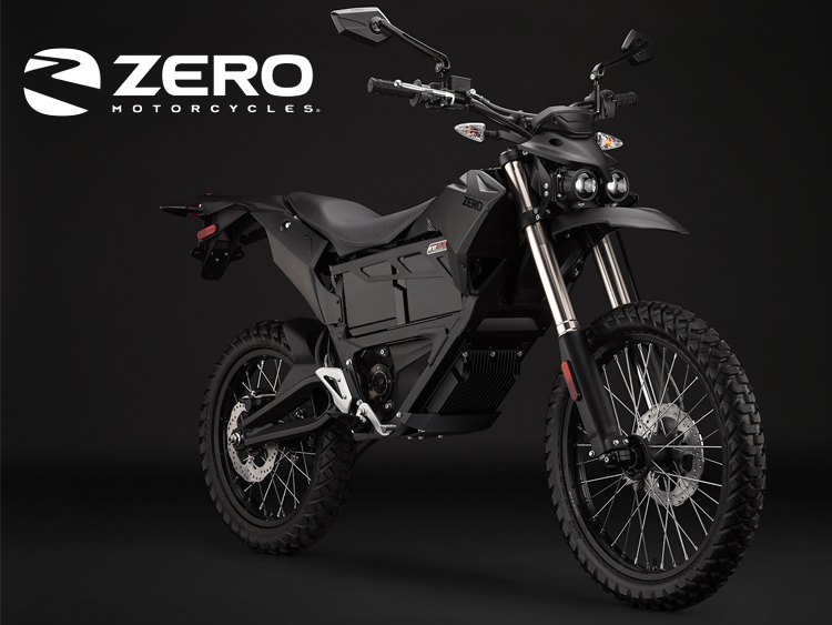
This manual covers the following motorcycle:
Zero FX Stealthfighter
One module power pack
• Z-Force® Li-Ion intelligent modular
• 27 hp (20 kW) Motor
• Spoke Wheels
Two module power pack
• Z-Force® Li-Ion intelligent modular
• 44 hp (33 kW) Motor
• Spoke Wheels
Version 1
Caution: Brake fluid may irritate eyes and skin. In case of contact, take the following actions:
• Eye Contact-rinse thoroughly with water
• Skin Contact-wash with soap and water
• If Ingested-contact a physician immediately
Version 1
Caution: Approved safety glasses and gloves should be worn when performing this procedure to reduce the chance of personal injury.
Version 1
Caution: Test ride the motorcycle under safe conditions. Do not attempt any maneuvers that could jeopardize the motorcycles control. Failure to adhere to these precautions could lead to serious personal injury and motorcycle damage.
Version 1
Notice: Avoid spilling brake fluid onto painted or other surfaces, electrical connections, wiring, or cables. Brake fluid will damage painted or other surfaces and cause corrosion to electrical components. If any brake fluid comes in contact with painted surfaces, immediately flush the area with water. If any brake fluid comes in contact with electrical connections, wiring, or cables, use a clean shop cloth to wipe away the fluid.
Version 1
Notice: Replacement fasteners must be the correct part number for that application. Use the correct fastener in the correct location. Fasteners requiring the use of thread-locking compound are specified in the repair procedure; refer to the product manufacture for proper usage. Always use new lock nuts, lock washers and cotter pins. Do not use paints, lubricants, or corrosion inhibitors on fasteners or fastener contact surfaces unless specified in the procedure. Coatings affect fastener torque and joint clamping force and may damage the fastener
Version 1
Caution: Always perform the High Voltage Disabling procedure prior to servicing any High Voltage component or connection. Proper procedures must be followed.
Failure to follow the procedures may result in serious injury or death.
• Always verify that the high voltage has been disabled before working on or around high voltage components, wires, cables, or harnesses.
• Remove all metal objects such as rings and watches.
• Always tighten the high voltage terminal fasteners to the specified torque. Insufficient or excessive torque will cause malfunctions or damage.
• After finishing work on the high voltage system and before turning the key ON.
• Verify high voltage system integrity and that all connectors and covers are installed.
• Verify that all tools or loose components have been removed.
Caution: Exposure to high voltage can cause shock, burns, and even death. The high voltage components on the motorcycle should only be serviced by technicians familiar with the circuit/system operation. Refer to System Description and Operation.
High voltage components are identified by labels. Do not remove, open, take apart, or modify these components. High voltage cable or wiring has orange covering. Do not probe, tamper with, cut, or modify high voltage cable or wiring.
Version 1
Although unpacking the Zero motorcycle can be done by a single person, it is recommended to have a second person to help lift and remove your motorcycle from the crate base.
Outer Box Cover
• Cut and remove the two outer box retention straps.
• Unscrew stabilizer bar bolts, one on each side of outer box.
• Open box top and remove inner cardboard end reinforcement sleeves.
• Unscrew stabilizer bar from handlebar riser and remove.
• Unscrew lower crate cover retaining screws and washers.
• Lift or cut outer box away from motorcycle.
Inner Assembly
• Carefully remove plastic cover from motorcycle.
• Locate small parts box below motorcycle and put to the side. (This box contains important documentation, owner’s manual, keys.
• Remove power pack retaining frame rail.
• Remove power pack.
• Remove the tie down straps from crate base.
• Carefully lift rear portion of the motorcycle over the swingarm standoff and off crate base.
• Carefully lift front wheel out of crate base.
• Deploy kickstand (if equipped), lean motorcycle and inspect in accordance with delivery inspection sheet.
Recycling
The Zero Motorcycles shipping crate and packaging materials were designed to be completely recycled. Please cut down and recycle all cardboard, plastic, and metal materials in appropriate receptacles.
The tie down straps that accompanied your motorcycle can be reused as regular tie down straps for transporting your motorcycle.
Version 1
|
Zero Motorcycles FX Pre-Delivery Inspection
Motorcycle Serial/VIN number:________________________________
Power Pack number:______________________ Date:___________
Technician Section After Uncrating:
|
|
|
Initial:
|
Operation:
|
|
|
Verify front axle is fully inserted, and axle pinch bolts are at specified torque.
|
|
|
Verify that front brake caliper is centered over rotor and all mounting hardware is at specified torque.
|
|
|
Verify front wheel for free operation, verify that wheel is true.
|
|
|
Verify exterior lighting is working correctly.
|
|
|
Verify the front and rear tire pressure is correct.
|
|
|
Verify the headset/steering adjustment and that all fork bolts are at specified torque.
|
|
|
Verify that the wiring connector in the instrument cluster is fully inserted and locked.
|
|
|
Verify the wiring connections on the controller and the key switch plug are fully inserted and locked.
|
|
|
Verify comfortable bar angle and check all stem/upper clamp bolts are at specified torque.
|
|
|
Verify the throttle, brake lever and motor stop switch adjustment angle and at specified torque.
|
|
|
Verify smooth throttle operation.
|
|
|
Verify that all plastics are securely fastened and all rivnuts are secure in the frame.
|
|
|
Verify that the seat bolts are at specified torque.
|
|
|
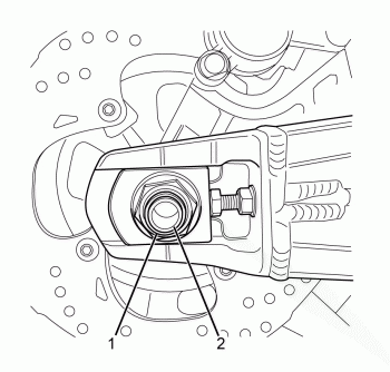
Verify that rear axle is fully inserted and end caps/pinch bolts are at specified torque.
|
|
|
Verify that rear brake caliper is centered over rotor and all mounting hardware is at specified torque.
|
|
|
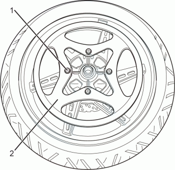
Verify rear wheel for free operation, verify that wheel is true.
|
|
|
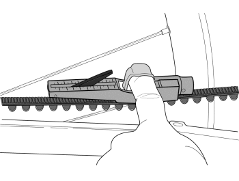
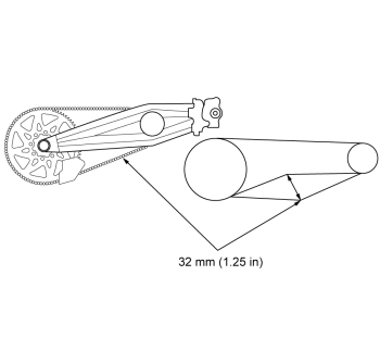
Verify that the belt tension is correct.
|
|
|
Verify main pivot bolts are at specified torque.
|
|
|
Verify audible click from solenoid when powered on.
|
|
|
Verify that battery gauge and power on LED are functional.
|
|
Road Test:
Caution: Before performing the Road Test, Refer to Road Testing Procedure.
|
|
|
|
Verify that front and rear brakes operate properly.
|
|
|
Verify throttle operation.
|
|
|
Verify smooth suspension operation and is correctly adjusted for the owners requirements.
|
|
|
Verify that the belt tension is correct after test ride.
|
|
Technician Signature:
|
|
|
Owners Section:
|
|
|
Initial:
|
Operation:
|
|
|
The technician has explained all safety warning labels.
|
|
|
I have received an owner's manual and supporting documents.
|
|
|
I understand the warranty as it has been explained to me.
|
|
|
I recognize that this is a high performance electric vehicle and requires special skills.
|
|
|
I accept that additional equipment is required to operate this motorcycle safely.
|
|
|
I will return the warranty registration card within the allotted time period.
|
|
|
I will never carry a passenger on a Zero FX motorcycle; it is designed for an operator only.
|
|
|
Know the limits of yourself and the machine on and off road.
|
|
|
I will never use alcohol or drugs while operating a Zero.
|
|
|
I will not allow a guest to operate a Zero without proper instruction.
|
|
|
I know to use the motor stop switch on the handlebar for emergency motor cut-off.
|
|
|
The technician who prepared this bike has instructed me
on the operation, maintenance, safety features, and warranty policy,
all of which I understand. I am also satisfied with the pre-delivery
set-up and inspection of my vehicle. I acknowledge that I have read all
the safety warnings and information on the product warning labels. I
understand the importance of reading the owners manual and supporting
documents completely and thoroughly. I was offered by my Certified
Service Center (CSC) to have the vehicle delivered at my expense to an
appropriate location for familiarization and self practice before I
operate it on my own.
|
|
Owners Signature:
|
|
Version 1
This manual covers the following motorcycles:
• Zero FX Stealth Fighter
-Belt Drive
-Street Tires
-Integrated Charger
-Lights
-Regenerative Braking
Identification Numbers
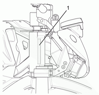
Loading image...

Legend
1. Identification Number
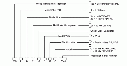
VIN Break Down
Loading image...

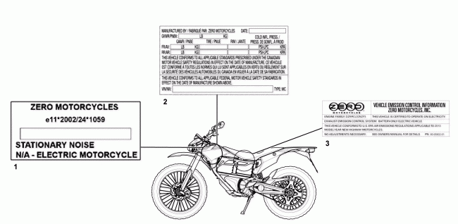
Location of Important Labels
Loading image...

Legend
1. VIN label (European Union) - certification label
2. VIN label (North America) - certification label shown
3. VECI (Vehicle Emission Control Information) label
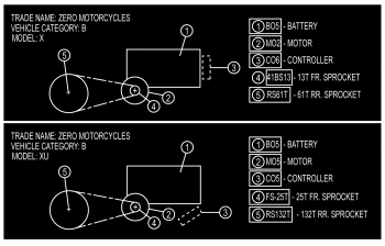
Anti-Tamper Control Label (Europe Only)
Loading image...

Version 1
Tools and Equipment
Use only Zero specified tools when servicing the motorcycle. The motorcycle contains a mix of metric and standard fasteners. Use of the incorrect tool or fastener may damage the motorcycle.
All dealers should have the following:
Special Tools:
• PN 85-05665 Controller Discharge Tool

Basic Tools:
• Gloves
• Safety glasses
• Spring loaded center punch
• 2.5mm, 3mm, 4mm, 5mm, 6mm, 8mm and 10mm T, L, and socket hex wrenches
• 7 mm L Allen wrench
• T25 Torx driver or socket bit
• Zip tie pulling/cutting gun
• 7mm, 8mm, 10mm, 13mm, 14mm, 15mm, 17mm, 21mm combination wrench
• Gear puller
• Rubber dead blow hammer
• Punch
• Flat and rat tail file
• Heavy duty 420 chain breaker
• Phillips and Flat head screw drivers
• 1/4" drive 1", 2”, and 3” socket extension
• 3/8" drive 1", 2", and 3" socket extension
• Needle nose pliers
• Adjustable pin spanner wrench
• 1/4" and 3/8” drive socket wrench
• Bicycle type headset press and removal tool
• Belt tension tool
• External snap ring pliers
• 7mm, 8mm, 10mm, 13mm, 1/4" and 3/8” drive socket
• 27mm socket
• Motorcycle head bearing press and removal tool
Equipment:
• Wheel truing stand
• Tire levers and or a tire changing machine
• Motorcycle stand/lift
Version 1
|
Description
|
ZF2.8
|
ZF5.7
|
|
Motor
|
||
|
Max torque
|
70 ft-lb (95 Nm)
|
70 ft-lb (95 Nm)
|
|
Max power
|
27 hp (20 kW) @ 3,700 RPM
|
44 hp (33 kW) @ 3,700 RPM
|
|
Type
|
Z-Force® 75-7 passively air-cooled, high efficiency, radial flux, permanent high-temp magnet, brushless motor
|
Z-Force® 75-7 passively air-cooled, high efficiency, radial flux, permanent high-temp magnet, brushless motor
|
|
Controller
|
High efficiency, 420 amp, 3-phase brushless controller with regenerative deceleration
|
High efficiency, 420 amp, 3-phase brushless controller with regenerative deceleration
|
|
Power System
|
||
|
Est. pack life to 80% (city)
|
79,000 miles (127,000 km)
|
158,000 miles (254,000 km)
|
|
Power pack
|
Z-Force® Li-Ion intelligent modular
|
Z-Force® Li-Ion intelligent modular
|
|
Max capacity
|
2.8 kWh
|
5.7 kWh
|
|
Nominal capacity
|
2.5 kWh
|
5.0 kWh
|
|
Charger type
|
650 W, integrated
|
650 W, integrated
|
|
Charge time (standard)
|
4.1 hours (100% charged) / 3.7 hours (95% charged)
|
7.8 hours (100% charged) / 7.4 hours (95% charged)
|
|
CHAdeMO charge time (accessory)
|
1.5 hours (100% charged) / 1 hour (95% charged)
|
1.5 hours (100% charged) / 1 hour (95% charged)
|
|
Quick 2x charger time (accessory)
|
1.9 hours (100% charged) / 1.4 hours (95% charged)
|
3.3 hours (100% charged) / 2.8 hours (95% charged)
|
|
Drivetrain
|
||
|
Transmission
|
Clutchless direct drive
|
Clutchless direct drive
|
|
Final drive
|
132T / 25T, Poly Chain® GT® Carbon™ belt
|
132T / 25T, Poly Chain® GT® Carbon™ belt
|
|
Chassis / Suspension / Brakes
|
||
|
Front suspension
|
43 mm inverted, aluminum slider forks with adjustable compression and rebound damping
|
43 mm inverted, aluminum slider forks with adjustable compression and rebound damping
|
|
Rear suspension
|
Piggy-back reservoir shock with adjustable spring preload, compression and rebound damping
|
Piggy-back reservoir shock with adjustable spring preload, compression and rebound damping
|
|
Front suspension travel
|
9.05 in (230 mm)
|
9.05 in (230 mm)
|
|
Rear suspension travel
|
8.94 in (227 mm)
|
8.94 in (227 mm)
|
|
Front brakes
|
Nissin 2 piston hydraulic, 240x4.5 mm disc
|
Nissin 2 piston hydraulic, 313x4 mm disc
|
|
Rear brakes
|
J-Juan 1 piston hydraulic, 240x4.5 mm disc
|
J-Juan 1 piston hydraulic, 240x4.5 mm disc
|
|
Front tire
|
3.00-21
|
3.00-21
|
|
Rear tire
|
4.10-18
|
4.10-18
|
|
Front wheel
|
1.60x21
|
1.60x21
|
|
Rear wheel
|
2.15x18
|
2.15x18
|
|
Dimensions
|
||
|
Wheel base
|
56.6 in (1,438 mm)
|
56.6 in (1,438 mm)
|
|
Seat height
|
34.7 in (881 mm)
|
34.7 in (881 mm)
|
|
Rake (1/3 suspension sag)
|
26.3 °
|
26.3 °
|
|
Trail (1/3 suspension sag)
|
4.5 in (114 mm)
|
4.5 in (114 mm)
|
|
Weight
|
||
|
Frame
|
19.5 lb (8.8 kg)
|
19.5 lb (8.8 kg)
|
|
Curb weight
|
238 lb (108 kg)
|
280 lb (127 kg)
|
|
Carrying capacity
|
382 lb (173 kg)
|
340 lb (154 kg)
|
Version 1
Where time and mileage are listed, follow the interval that occurs first.
Note: From 37,000 km (24,000 miles) or 36 months, repeat the maintenance intervals starting from 13,000 km (8,000 miles) or 12 months.
|
No. |
ITEM |
ROUTINE |
EVERY RIDE |
INITIAL |
TIME INTERVALS |
||||
|
1,000 km (600 mi) or 1 month |
7,000 km (4,000 mi) or 6 months |
13,000 km (8,000 mi) or 12 months |
19,000 km (12,000 mi) or 18 months |
25,000 km (16,000 mi) or 24 months |
31,000 km (20,000 mi) or 30 months |
||||
|
1 |
Front Brake | • Check operation, and for fluid leakage. • Replace brake pads if necessary. |
● |
● |
● |
● |
● |
● |
● |
|
2 |
Rear Brake | • Check operation, and for fluid leakage. • Replace brake pads if necessary. |
● |
● |
● |
● |
● |
● |
● |
|
3 |
Wheels | • Check runout and for damage. Replace if necessary. |
● |
● |
● |
● |
● |
||
|
4 |
Tires | • Check tread depth and for damage. Replace if necessary. • Check air pressure. Correct if necessary. |
● |
● |
● |
● |
● |
● |
|
|
5 |
Wheel Bearings | • Check bearings for smooth operation. Replace if necessary. |
● |
● |
● |
● |
● |
||
|
6 |
Drive Chain (optional) | • Check chain slack/alignment and condition. • Adjust and lubricate chain with chain lubricant thoroughly. • Replace worn chain and sprockets. |
● |
Every 1,000 km (600 mi) and after washing the motorcycle or riding in the rain. | |||||
|
7 |
Steering Bearings | • Check bearing assembly for looseness. |
● |
● |
● |
● |
Repack |
● |
|
|
8 |
Chassis Fasteners | • Check all chassis fittings and fasteners. Correct if necessary. |
● |
● |
● |
● |
● |
||
|
9 |
Front Fork | • Check operation and for oil leakage. • Service/rebuild if necessary. |
● |
● |
● |
● |
● |
● |
|
|
10 |
Rear Shock Absorber Assembly | • Check operation and for oil leakage. Replace if necessary. |
● |
● |
● |
● |
● |
● |
|
|
11 |
Throttle Grip | • Check operation and free play. |
● |
● |
● |
● |
● |
● |
|
|
12 |
Kickstand Pivots |
• Check operation. • Apply silicon grease lightly. |
● |
● |
● |
● |
● |
||
|
13 |
Kickstand Switch | • Check operation and replace if necessary. |
● |
● |
● |
● |
● |
● |
|
|
14 |
Drive Belt |
• Check belt slack and condition. • Replace the belt every 40,000 km (25,000 mi). |
● |
||||||
|
15 |
Front Brake Lever Pivot Shaft | • Apply silicon grease (all-purpose grease) lightly. |
● |
● |
● |
● |
● |
||
Version 1
Important: Using the following steps of the vibration diagnostic process will help you to effectively narrow-down and pin-point the search for the specific source of a vibration concern and to arrive at an accurate repair.
Vibration Diagnostic Process
1. Gather specific information on the customer's vibration concern.
2. Perform the road testing steps in sequence as identified in Road Testing Procedure in order to duplicate the customer's concern and evaluate the symptoms of the concern under changing conditions. Observe what the vibration feels like and what it sounds like. Observe when the symptoms first appear, when they change, and when they cease.
3. Determine if the customer's vibration concern is truly an abnormal condition or something that is potentially an operating characteristic of the motorcycle.
4. Systematically eliminate or 'rule-out' possible motorcycle systems.
5. Focus diagnostic efforts on the remaining motorcycle system and systematically eliminate or "rule-out" possible components of that system.
6. Make a repair on the remaining component, or components, which have not been eliminated systematically, and must therefore be the cause of the vibration.
7. Verify that the customer's concern has been eliminated or at least brought to an acceptable level.
8. Again perform the road testing steps in sequence in order to verify that the vehicle did not have more than one vibration occurring.
Preliminary Visual/Physical Inspection
• Inspect for aftermarket equipment and modifications, which could affect the operation of the motorcycles rotating component systems.
• Inspect the easily accessible or visible components of the motorcycles rotating component systems for obvious damage or conditions, which could cause the symptom.
• Inspect the tire inflation pressures for the proper pressure.
Version 1
Caution: Refer to Road Test Caution in General Information.
Caution: Road test a motorcycle under safe conditions and while obeying all traffic laws. Do not attempt any maneuvers that could jeopardize the control of the motorcycle. Failure to adhere to these precautions could lead to serious personal injury and motorcycle damage.
Before the road test, ensure the following:
• The exterior lighting is working correctly.
• Tire pressure is correct.
During the road test:
• Perform the test only when traffic conditions permit.
• Operate the motorcycle in a controlled, safe manner.
• Observe all traffic regulations.
• Observe any unusual vibrations.
o When braking
o When coasting
o When accelerating
o When regen braking
• Observe any unusual sounds.
o When braking
o When coasting
o When accelerating
o When regen braking
Choose different road surfaces when test driving to verify that the condition is not related to road surfaces. Observe where the problem condition is located: Front, back or under the motorcycle. If the condition is something that is heard or felt, driving a similarly equipped motorcycle may determine if the issue is an operating characteristic of the motorcycle.
Version 1
For the purposes of these warranties, “proper use” means only the use of a motorcycle in the manner intended for a single rider with proper safety equipment as described in the Owner’s Manual on safe and dry surfaces in accordance with local regulations. “Proper use” also means charging the Power Pack after each use and storing it in a fully charged state, or recharging it every 15 days or keeping it on the charger when in storage or out of regular use.
Version 1
What Does This Limited Warranty Cover?
Zero Motorcycles Inc. ("Zero") warrants that all factory manufactured 2014 Zero S, Zero DS, Zero SR and Zero FX motorcycles are free from defects in material and workmanship during the period of this Limited Warranty.
This Limited Warranty covers parts, including the motor, motor controller, frame, swing arm, fork, rear shock, brake assemblies, wheels and electrical sub-assemblies, and approved Zero accessories installed at the time of purchase by an authorized Zero dealer.
This Limited Warranty also covers the following items, collectively referred to as "Power Packs":
• ZF2.8 Power Pack Modules on the Zero FX.
• The Z-Force® Power Tank and ZF2.8 Power Pack Modules that are purchased within 30 days of the original motorcycle in service date. Z-Force Power Tanks or ZF2.8 Power Pack Modules purchased after this 30-day period will carry the standard Zero Accessory Limited Warranty of 1 year and unlimited miles.
• ZF8.5 and ZF11.4 Z-Force® Li-Ion Power Packs on the Zero S, Zero DS and the Zero SR.
This Limited Warranty covers all components of the Power Packs that are included as a part of the Z-Force® Power Pack, including the battery, integrated battery management system, internal wiring, and internal structures.
Who Does This Limited Warranty Cover?
This Limited Warranty applies to all original owners who submit the warranty registration card within the required time period as printed on the registration card.
This Limited Warranty may only be transferred to new owners with payment of a $50 processing fee and submission of a new registration card by the new owner. Additional information regarding transferring this Limited Warranty may be found at http://www.zeromotorcycles.com/owner-resources/ or by contacting Zero at the following:
Via phone at (888) 841-8085 or +31 (0) 72 5112014 (Europe); via e-mail at support@zeromotorcycles.com, or via letter directed to:
North America
Zero Motorcycles Inc.
380 El Pueblo Road
Scotts Valley, CA 95066
USA
Europe
Zero Motorcycles Europe
Fluorietweg 12D
Alkmaar, Noord Holland 1812RR
Netherlands
(U.S. and International Patents and Trademarks Pending)
What is the Coverage Period of This Limited Warranty?
The duration of this Limited Warranty for 2014 Zero S, Zero DS, Zero SR and Zero FX motorcycle models, not including the Power Packs, is a period of 2 years from the original "in service date." The "in service date" is the date that the authorized dealer performs a pre-delivery inspection ("PDI") and delivers the motorcycle to the customer. In the event these events occur on different dates, the later date shall be the “in service date.”
The duration of this Limited Warranty for Power Packs, not including the Power Pack’s outer case, is as follows:
• 5 years or 50,000 miles, whichever occurs first, from the "in service date" for ZF2.8 Power Pack Modules on the Zero FX.
• 5 years or 50,000 miles, whichever occurs first, from the "in service date" for the Z-Force Power Tank on the Zero S, Zero DS and the Zero SR.
• 5 years or 100,000 miles, whichever occurs first, from the "in service date" for ZF8.5 and ZF11.4 Z-Force Li-Ion Power Packs on the Zero S, Zero DS and the Zero SR.
The Power Pack’s outer case is not covered under the Power Pack Limited Warranty duration terms above. Instead, the Power Pack’s outer case is covered for a period of 2 years from its "in service date."
What is Not Covered By This Limited Warranty?
Due to the battery chemistry, there is a normal, expected reduction in range/capacity that Power Packs can yield over time and usage. Depending on use and storage conditions, Power Packs will degrade during the duration of this Limited Warranty period. Zero will only repair or replace pursuant to this limited warranty a Power Pack that exhibits a nominal storage capacity reduction of greater than 20% of the published nominal capacity, as measured by an authorized Zero dealer. To check the capacity of a Power Pack, an authorized Zero dealer can perform a battery management system log data extraction, which will confirm if a reduction is within expected norms.
Further, this Limited Warranty only covers 2014 Zero S, Zero DS, Zero SR and Zero FX motorcycles or Power Packs that are operated according to "proper use" and "under normal operating conditions." For purposes of this exclusion, the following definitions apply:
• "Normal operating conditions" require routine care and maintenance of the 2014 Zero S, Zero DS, Zero SR and Zero FX motorcycles and Power Packs as described in the Owner’s Manual.
• "Proper use" means only the use of a motorcycle in the manner intended for a rider and passenger on a Zero S, Zero SR, Zero DS and Zero FX with proper safety equipment as described in the Owner’s Manual, in accordance with local regulations.
• "Proper use" also means charging the Power Pack after each use and storing it in a fully charged state, or recharging it every 30 days, or keeping it on the charger when in storage or not in regular use.
In addition, this Limited Warranty does not cover:
• The cost of parts and labor involved in any routine care and maintenance and/or the replacement of parts due to normal wear and tear, use, or deterioration, including but not limited to: tires, brake pads and rotors, fork seals, grips, foot pegs, and the seat;
• The replacement of fluids, unless their replacement is a necessary part of warranty service on a covered component;
• Wheels on off-road bikes once they have been ridden.
• Any cosmetic concerns that arise as a result of environmental conditions, owner abuse, misuse, lack of routine care and maintenance, and/or improper use;
• Parts or components damaged by use or operation under abnormal circumstances or contrary to the requirements described in the Zero Motorcycle Owner’s Manual.
• Zero motorcycles and Power Packs used for racing or other competitive events;
• Zero motorcycles and Power Packs misused or improperly operated;
• Damage, malfunctions, or performance problems caused by modifications or alterations to 2014 Zero S, Zero DS, Zero SR, and Zero FX motorcycles and/or Power Packs – including modifications or alterations performed by an authorized Zero dealer – that cause the Zero motorcycle or Power Pack to fail;
• Damage, malfunctions, or performance problems caused by aftermarket accessories installed on a Zero motorcycle or Power Pack after the "in service date,” or caused by aftermarket accessories installed by someone other than an authorized Zero dealer;
• Damage, malfunctions, or performance problems caused by the improper repair of the motorcycle, installation of any parts or accessories not sold or approved by Zero, the installation and use of any parties or accessories that alter the motorcycle’s specifications from those set by Zero, or the use of new or used parts not approved by Zero;
• Damage, malfunctions, or performance problems caused by fire, collision, accident, or improper storage;
• Damage, malfunctions, or performance problems caused by continued operation of the motorcycle after a warning light, gauge reading, or other warning indicates a mechanical or operational problem;
• Motorcycles severely damaged or declared to be a total loss by an insurer, or motorcycles substantially reassembled from or repaired with parts obtained from another used motorcycle;
• Damage, malfunctions, or performance problems caused by the failure to follow recommended maintenance requirements as set forth in the Zero Owner’s Manual; and,
• Damage, malfunctions, or performance problems caused by airborne industrial pollutants (e.g., acid rain), bird droppings, tree sap, stones, flood water, windstorms, or other similar occurrences;
Further, this Limited Warranty does not apply to Zero motorcycles or parts and accessories that are not imported or distributed by Zero.
Other Expenses: This Limited Warranty does not cover any incidental or consequential damages, including loss of value of the motorcycle, lost profits or earnings, out-of-pocket expenses for substitute transportation or lodging, expenses associated with returning the covered product to a authorized service facility or dealer, towing and/or roadside assistance expenses, expenses associated with returning the covered product back to its owner, mechanic’s travel time or communication charges, loss or damage to personal property, loss or time, or inconvenience. (Some states do not allow the exclusion or limitation of incidental or consequential damages, so this limitation or exclusion may not apply to you. This warranty gives you specific legal rights and you may also have other rights, which vary from state to state.)
This Limited Warranty is the only express warranty made in connection with the sale of this Zero Motorcycle model. Any implied warranty, including any warranty of merchantability or warranty of fitness for a particular purpose is limited in duration to the stated period of this written warranty. (Some states do not allow limitations on how long an implied warranty lasts, so this limitation may not apply to you.)
Zero does not assume – or authorize any person to assume – any other obligation or liability on its behalf.
What Will Zero Do Under This Limited Warranty?
During the duration of this Limited Warranty, an authorized Zero dealer will repair or replace (at Zero’s discretion), without charge, any 2014 Zero S, Zero DS, Zero SR and Zero FX models, Power Packs, or parts that are covered by this Limited Warranty and found by Zero or an authorized Zero dealer to be defective in factory materials or workmanship.
How Do You Obtain Service Under This Limited Warranty?
Warranty services may be obtained by contacting a local authorized Zero dealer. Please see the dealer locator on www.zeromotorcycles.com for the nearest location.
Warranty services may also be obtained by contacting Zero via telephone at (888) 841-8085 or +31 (0) 72 5112014 (Europe), via e-mail at support@zeromotorcycles.com, or via written letter directed to the following:
North America
Zero Motorcycles Inc.
380 El Pueblo Road
Scotts Valley, CA 95066
USA
Europe
Zero Motorcycles Europe
Fluorietweg 12D
Alkmaar, Noord Holland 1812RR
Netherlands
(U.S. and International Patents and Trademarks Pending)
In any written or telephonic communication, please state the specific nature of and any circumstances leading to the problem.
What are Your Responsibilities as a Customer?
As the owner of a product covered by this Limited Warranty, it is your responsibility to read and understand the Owner’s Manual, this Limited Warranty, and all product warnings before operating your Zero motorcycle. Serious injury or death can result from improper operation or failure to observe warnings and safety instructions on any motorcycle.
Further, it is also your responsibility to:
• Perform all recommended and necessary routine care and maintenance and engage in proper use of your Zero motorcycle and Power Pack as detailed in the Owner’s Manual.
• Learn and obey all federal, state, and local laws governing the operations of a motorcycle, generally, and an electric motorcycle, specifically.
• At all times when operating a Zero motorcycle wear proper safety equipment and clothing, including but not limited to helmet, goggles, and appropriate boots.
What Other Limitations or Disclaimers Apply to this Limited Warranty?
The following additional limitations and disclaimers apply to this Limited Warranty:
• Zero Motorcycles reserves the right to change or improve the design of any Zero motorcycle, Power Pack, or any other Zero parts (collectively, "Zero products") at any time, without assuming any obligation to modify any Zero products previously manufactured or sold.
• The purchaser acknowledges that there is an inherent risk in the operation of motorcycles. This Limited Warranty does not cover – and Zero cannot assume responsibility for – any injury arising from the unsafe or improper operation of Zero products, or the user’s failure to comply with instructions, care and maintenance requirements, warnings, and safety precautions.
• The original registered owner or subsequent registered transferee as documented on the Zero motorcycle warranty registration form is responsible for conveying the Owner’s Manual and all safety warnings, instructions, and Limited Warranty if the unit is sold, loaned, or otherwise transferred to another person. Zero Motorcycles Inc. does not assume or authorize anyone to assume for them any other obligation.
Warranty Procedures:
Warranty services may be obtained by contacting a local authorized Zero dealer. Please see the dealer locator on www.zeromotorcycles.com for the nearest location.
Warranty services may also be obtained by contacting Zero via telephone at (888) 841-8085 or +31 (0) 72 5112014 (Europe), via e-mail at support@zeromotorcycles.com, Service may also be available from a local Zero Motorcycles dealer; please see the locator on www.zeromotorcycles.com for the nearest location.
In any written or telephonic communication, please state the specific nature of and any circumstances leading to the problem.
North America
Zero Motorcycles Inc.
380 El Pueblo Road
Scotts Valley, CA 95066
USA
Europe
Zero Motorcycles Europe
Fluorietweg 12D
Alkmaar, Noord Holland 1812RR
Netherlands
(U.S. and International Patents and Trademarks Pending)
Transfer of Ownership and Warranty?
When it comes time to sell your Zero motorcycle, please visit the Zero Motorcycles website and access the owner resources section to fill out the on-line transfer of ownership and warranty form. This must be performed to allow Zero Motorcycles the ability to contact the new owner in the unlikely event of a safety related issue. Use the URL address below or feel free to contact the Zero Motorcycles Customer Service department for assistance.
North America
Phone: (888) 841-8085
Monday-Friday
8am to 5pm Pacific Time
E-mail: support@zeromotorcycles.com
Europe
Phone: +31 (0) 72 5112014
E-mail: support@zeromotorcycles.com
For updates and additional information about your motorcycle, visit the owner resources section of Zero Motorcycles website:
http://www.zeromotorcycles.com/owner-resources/
Version 1
Zero Motorcycles Inc. can be contacted via the contact methods listed below. Please have available the following, as it is essential to effectively and efficiently answer your questions or resolve your concerns.
• Owner’s name and address
• Owner’s telephone number
• Vehicle identification number (VIN)
• Date of purchase
• Power Pack serial number
• Motor serial number
An owner information chart is provided in the Zero Motorcycles Owner's Manual to record this information.
North American and Canada:
Zero Motorcycles
380 El Pueblo Rd.
Scotts Valley, California 95066
USA
Phone: (888) 786-9376
Monday-Friday
8am to 5pm Pacific Time
Europe:
Zero Motorcycles BV
Fluorietweg 12D
Alkmaar, 1812 RR
NL
E-mail: service@zeromotorcycles.com
24 hours
International Contacts:
For the most up to date information, please refer to http://www.zeromotorcycles.com/contact
Version 1
|
Application
|
Specification
|
|
|
Type of Material
|
Part Number
|
|
| Axle End Cap Bolts | Threadlock | 242 |
| Axle Pinch Bolts | Threadlock | 242 |
| Brake Fluid | Fluid | DOT 4 |
| Brake Rotor Bolts | Threadlock | 242 |
| Caliper Bolts (Front) | Threadlock | 242 |
| Caliper Bolts (Rear) | Threadlock | 242 |
| Fork Bearings | Dupont™ Teflon® Service Grease | — |
| Lower Chain Guide Bolts | Anti-seize | — |
| Master Cylinder Shield Bolts | Threadlock | 242 |
| Motor Shaft | Threadlock | 680 |
| Motor Shaft Bolt | Threadlock | 271 |
| Rear Axle End Cap Bolts | Threadlock | 242 |
| Rear Brake Pedal Pivot Bolt | Threadlock | 242 |
| Shock Bolts | Anti-seize | — |
| Triple Tree Pinch Bolts | Threadlock | 242 |
Version 1
CAUTION: Under-inflation is the most
common cause of tire failure and may result in severe tire cracking,
tread separation, “blowout,” or unexpected loss of motorcycle control
causing personal injury and possible death.
The tire pressure is checked using an accurate gauge when the tires are
cold. This means that the tires have not been ridden on for 3 hours.
Always replace the valve stem cap when finished.
|
MODEL
|
FRONT
|
REAR
|
|
FX
|
200 kpa
(29 psi)
|
186 kpa
(27 psi)
|
Version 1
|
PART
|
NUMBER
|
|
Headlight Bulb
|
H3 (55 watt)
|
|
Turn Signal Light Bulb (amber)
|
RY10W (10 watt)
|
|
Brake/Tail Light Bulb
|
LED (replace entire unit)
|
|
Front Running Light Bulb
|
W3W (3 watt)
|
Version 1
Whenever there is an excessive amount of current flowing through a
circuit the fusible element will melt and create an open or incomplete
circuit. Fuses are a one-time protection device and must be replaced
each time the circuit is overloaded. Replace the fuse with one of equal
current and voltage rating. If the fuse melts repeatedly, inspect the
circuit for an overload or short.
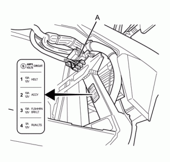
Fuse Center Location
12 Volt
The 12 volt fuse center is located in front of the front power pack, on the right side of the frame. The fuse center has a protective cover that must first be removed to gain access to the fuses. To remove the cover, squeeze the tabs together and lift off the cover (A).
|
Fuse Number
|
Amp
|
Circuits Controlled
|
|
1
|
10
|
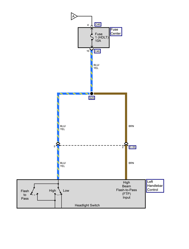
Voltage to Splice S25
• Headlight Switch
|
|
2
|
10
|
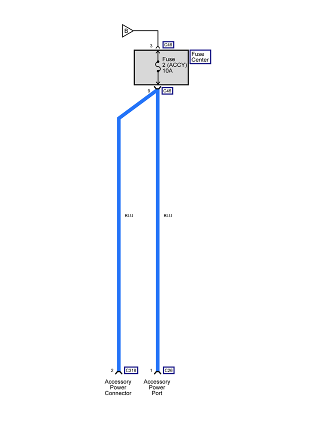
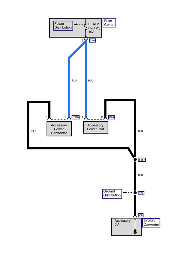
• Accessory Power Port
• Accessory Power Connector
|
|
3
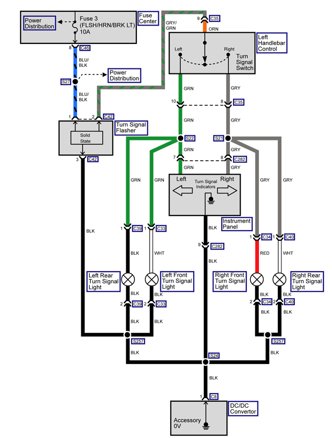
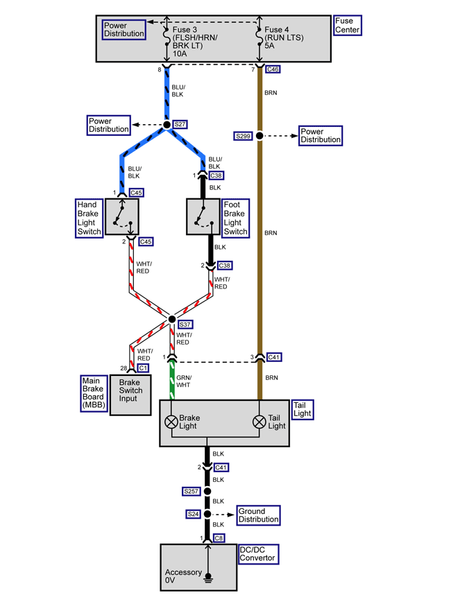
|
10
|
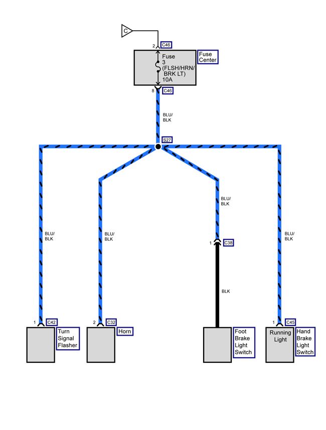
Voltage to Splice S27
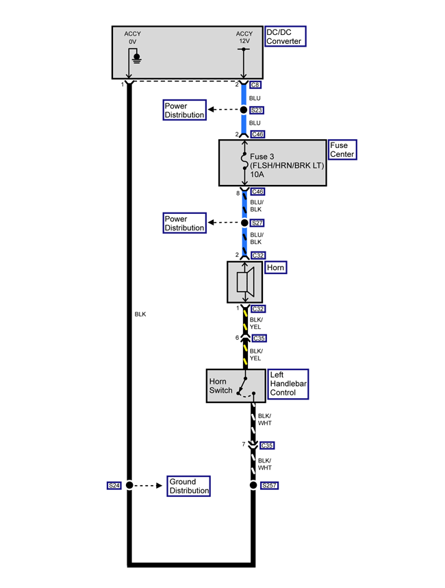
• Horn • Turn Signal Flasher • Brake Switches
|
|
4
|
5
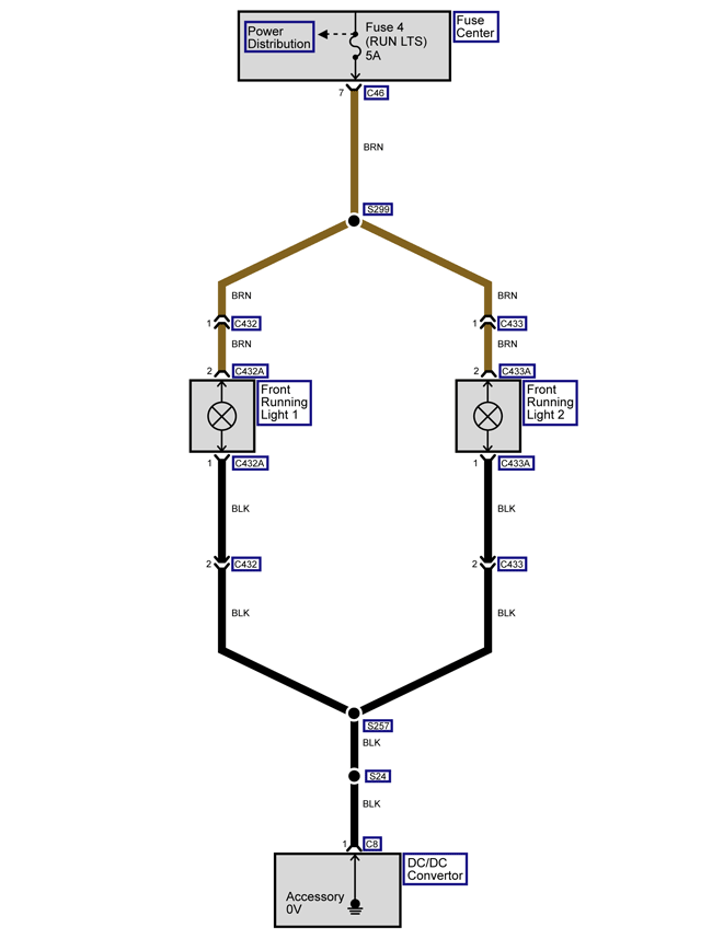
|
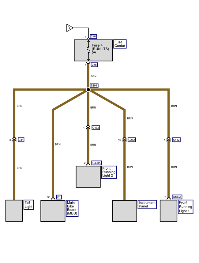
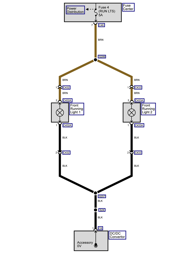
Voltage to Splice S299
• Instrument Panel • Tail Light • Main Bike Board
•Running Light 1 and 2
|

Inline Fuse:
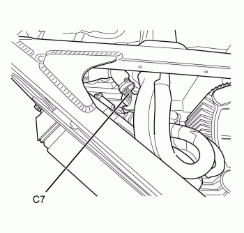
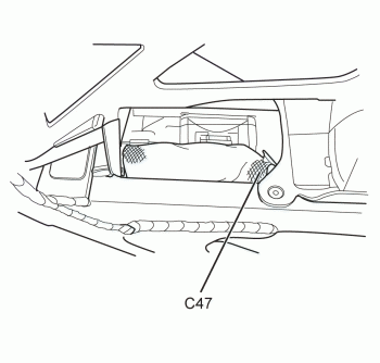
There are 3 inline 12 volt fuses, these are inside the harness covering.
DC/DC Converter Fuse
|
Fuse Number
|
Amp
|
Circuits Controlled
|
|
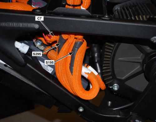
C7
|
4
|
DC/DC Converter
|

Note: Trim panel removed for clarity.
Below the front power pack inside the harness cover.
Main Bike Board (MBB) Fuse
|
Fuse Number
|
Amp
|
Circuits Controlled
|
|
C47
|
4
|
Main Bike Board (MBB)
|

Note: Trim panel removed for clarity.
Below the front power pack, across from the MBB, inside the harness cover.
Charger Control Unit (CCU) Fuse
|
Fuse Number
|
Amp
|
Circuits Controlled
|
|
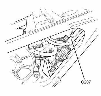
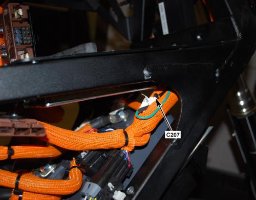
C207
|
10
|
Charger Control Unit (CCU)
|

Note: Trim panel removed for clarity.
Below the front power pack, across from the MBB, inside the harness cover.
Version 1
|
Application
|
Specification
|
|
|
Type of Material
|
Part Number
|
|
| Axle End Cap Bolts | Threadlock | 242 |
| Axle Pinch Bolts | Threadlock | 242 |
| Brake Fluid | Fluid | DOT 4 |
| Brake Rotor Bolts | Threadlock | 242 |
| Caliper Bolts (Front) | Threadlock | 242 |
| Caliper Bolts (Rear) | Threadlock | 242 |
| Fork Bearings | Dupont™ Teflon® Service Grease | — |
| Lower Chain Guide Bolts | Anti-seize | — |
| Master Cylinder Shield Bolts | Threadlock | 242 |
| Motor Shaft | Threadlock | 680 |
| Motor Shaft Bolt | Threadlock | 271 |
| Rear Axle End Cap Bolts | Threadlock | 242 |
| Rear Brake Pedal Pivot Bolt | Threadlock | 242 |
| Shock Bolts | Anti-seize | — |
| Triple Tree Pinch Bolts | Threadlock | 242 |
Version 1
CAUTION: Under-inflation is the most
common cause of tire failure and may result in severe tire cracking,
tread separation, “blowout,” or unexpected loss of motorcycle control
causing personal injury and possible death.
The tire pressure is checked using an accurate gauge when the tires are
cold. This means that the tires have not been ridden on for 3 hours.
Always replace the valve stem cap when finished.
|
MODEL
|
FRONT
|
REAR
|
|
FX
|
200 kpa
(29 psi)
|
186 kpa
(27 psi)
|
Version 1
|
PART
|
NUMBER
|
|
Headlight Bulb
|
H3 (55 watt)
|
|
Turn Signal Light Bulb (amber)
|
RY10W (10 watt)
|
|
Brake/Tail Light Bulb
|
LED (replace entire unit)
|
|
Front Running Light Bulb
|
W3W (3 watt)
|
Version 1
Whenever there is an excessive amount of current flowing through a
circuit the fusible element will melt and create an open or incomplete
circuit. Fuses are a one-time protection device and must be replaced
each time the circuit is overloaded. Replace the fuse with one of equal
current and voltage rating. If the fuse melts repeatedly, inspect the
circuit for an overload or short.
Fuse Center Location
12 Volt
The 12 volt fuse center is located in front of the front power pack, on the right side of the frame. The fuse center has a protective cover that must first be removed to gain access to the fuses. To remove the cover, squeeze the tabs together and lift off the cover (A).
|
Fuse Number
|
Amp
|
Circuits Controlled
|
|
1
|
10
|
Voltage to Splice S25
• Headlight Switch
|
|
2
|
10
|
• Accessory Power Port
• Accessory Power Connector
|
|
3
|
10
|
Voltage to Splice S27
• Horn • Turn Signal Flasher • Brake Switches
|
|
4
|
5
|
Voltage to Splice S299
• Instrument Panel • Tail Light • Main Bike Board
•Running Light 1 and 2
|

Inline Fuse:
There are 3 inline 12 volt fuses, these are inside the harness covering.
DC/DC Converter Fuse
|
Fuse Number
|
Amp
|
Circuits Controlled
|
|
C7
|
4
|
DC/DC Converter
|

Note: Trim panel removed for clarity.
Below the front power pack inside the harness cover.
Main Bike Board (MBB) Fuse
|
Fuse Number
|
Amp
|
Circuits Controlled
|
|
C47
|
4
|
Main Bike Board (MBB)
|

Note: Trim panel removed for clarity.
Below the front power pack, across from the MBB, inside the harness cover.
Charger Control Unit (CCU) Fuse
|
Fuse Number
|
Amp
|
Circuits Controlled
|
|
C207
|
10
|
Charger Control Unit (CCU)
|

Note: Trim panel removed for clarity.
Below the front power pack, across from the MBB, inside the harness cover.
Version 1
|
Application
|
Specification
|
|
|
Metric
|
English
|
|
|
Brushless Motor Controller Cable Bolt
|
11 N•m
|
8 lb ft
|
|
Brushless Motor Controller Upper Bracket Bolts
|
11 N•m
|
8 lb ft
|
|
Controller Nuts and Bolts
|
1.3 N•m
|
12 lb in
|
|
Front Fairing Bolts
|
1.3 N•m
|
12 lb in
|
|
Front Fender Bolts
|
2 N•m
|
22 lb in
|
|
Instrument Panel Nuts
|
4 N•m
|
36 lb ft
|
|
Seat Bolts
|
15 N•m
|
11 lb ft
|
Version 1

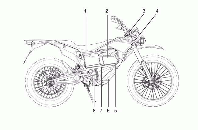
Legend
1. Rear Power Pack
2. Front Power Pack
3. Integrated Power Pack Chargers
4. Charger Control Unit (CCU)
5. Main Bike Board (MBB)
6. Brushless Motor Controller
7. DC/DC Converter
8. Brushless Motor
Version 1

Version 1

Version 1
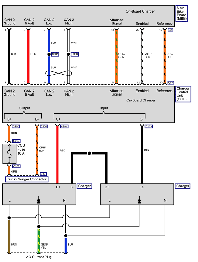
|
SCH2515
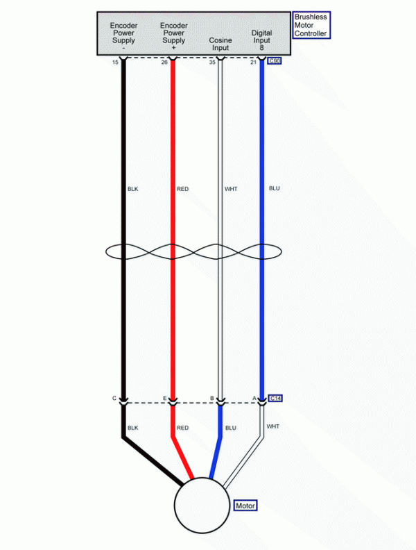
Loading image...

|
Version 1
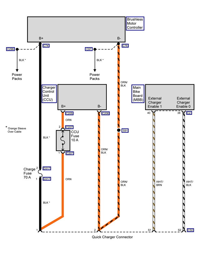
|
SCH2516
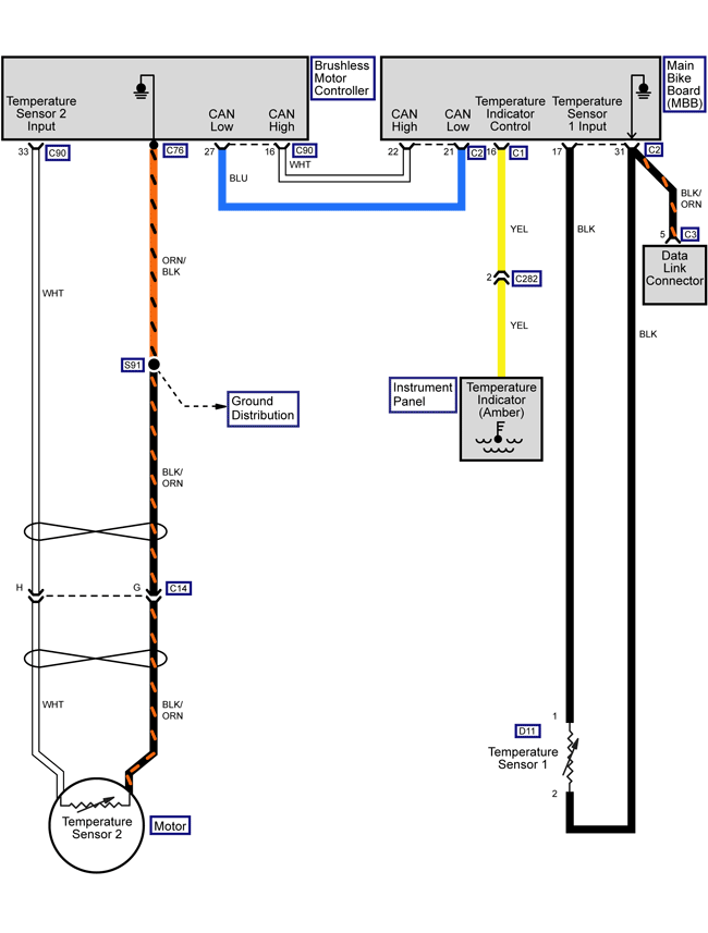
Loading image...

|
Version 1
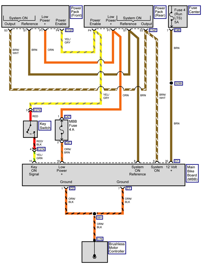
|
SCH2521
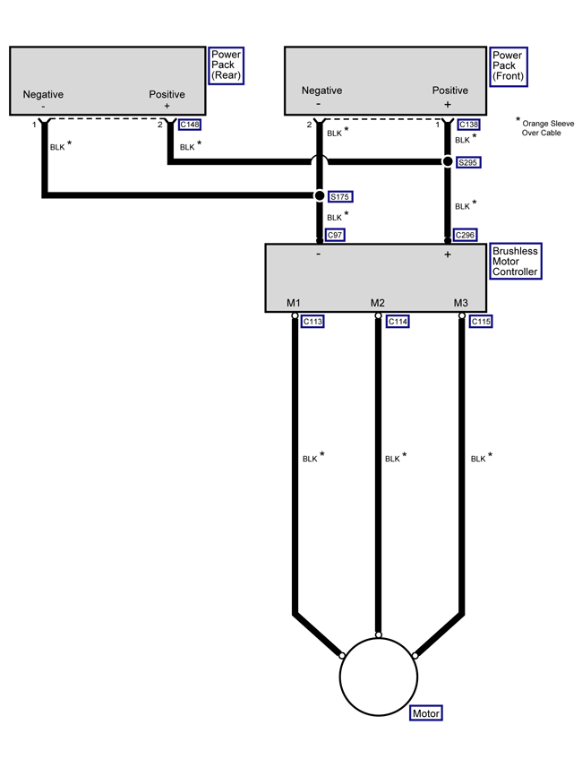
Loading image...

|
Version 1
|
SCH2515
Loading image...

|
Version 1
|
SCH2516
Loading image...

|
Version 1
|
SCH2521
Loading image...

|
Version 1
|
SCH2525
Loading image...

|
Version 1
|
SCH2491
Loading image...

|
Version 1
|
SCH2524
Loading image...

|
Version 1
|
SCH2522
Loading image...

|
Version 1
|
SCH2533
Loading image...

|
Version 1
|
SCH2534
Loading image...

|
Version 1
|
SCH2528
Loading image...

|
Version 1
|
SCH2526
Loading image...

|
Version 1
|
SCH2529
Loading image...

|
Version 1
|
SCH2529
Loading image...

|
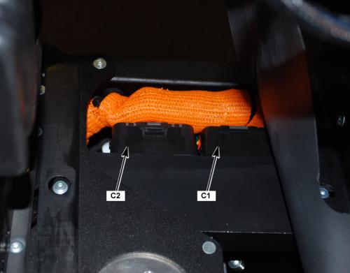
Version 1
|
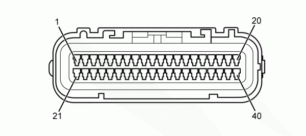
C1 Main Bike Board Connector Face View |
|||
|
18007
|
|||
|
Connector Part Information |
|
||
|
Pin |
Wire Color |
Function |
|
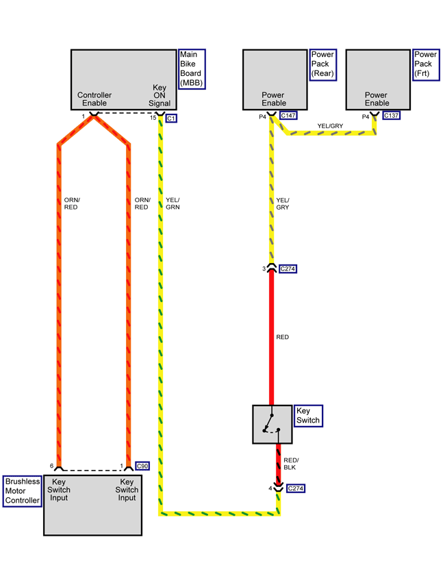
| 1 | ORN/RED | Motor Controller Enable | |
| 2 | ORN/BLU | Motor Controller Digital Input 1 | |
| 3 | ORN/VIO | Motor Controller Digital Input 3 | |
| 4-6 | — | Not Used | |
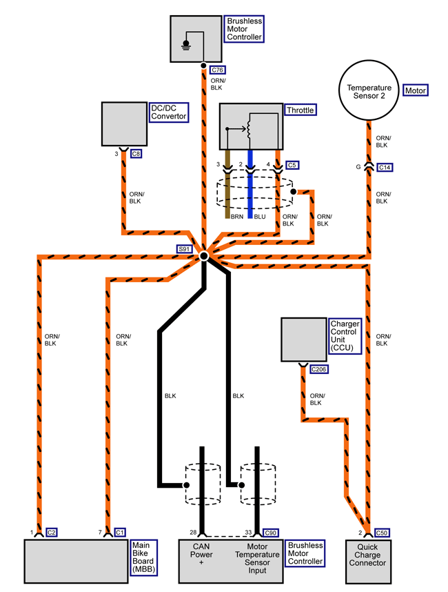
| 7 | ORN/BLK | Power Pack Ground | |
| 8 | BRN | System ON Signal | |
| 9 | BRN/WHT | System ON Output | |
| 10 | — | Not Used | |
| 11 | YEL/BLK | Kickstand Switch Signal | |
| 12 | ORN/BLK | Kickstand Switch Ground | |
| 13 | — | Not Used | |
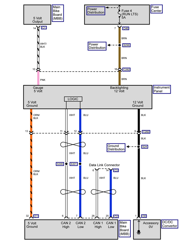
| 14 | WHT/BLK | Fuel Gauge 5V Reference | |
| 15 | YEL/GRN | Key ON 12V | |
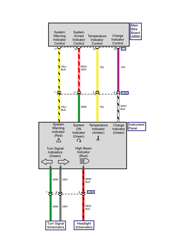
| 16 | YEL | Temperature Warning Lamp Control | |
| 17 | YEL/BLK | Warning Lamp Control | |
| 18 | ORN/BRN | MBB Low Power | |
| 19 | ORN/GRY | Motor Controller Neutral | |
| 20 | ORN/RED | DC/DC Converter Enable | |
| 21 | ORN/YEL | Motor Controller Digital Input 2 | |
| 22 | BLK/WHT | Battery Throttle Enable | |
| 23 | RED | Motor Stop Switch 5V | |
| 24 | WHT | Motor Stop Switch IN | |
| 25-26 | — | Not Used | |
| 27 | RED | Kickstand Switch Signal | |
| 28 | WHT/RED | Brake Switch Input | |
| 29 | BLK | 12 Volt Ground | |
| 30 | BRN | 12 Volt Positive | |
| 31 | — | Not Used | |
| 32 | ORN/BLK | Instrument Cluster Light Ground | |
| 33 | VIO | Charge Indicator Control | |
| 34 | RED/WHT | Armed Indicator Light Control | |
| Under the Cover, Below the Front Power Pack |
|
COM1458
Loading image...

|
Version 1
|
C2 Main Bike Board Connector Face View |
||
|
CON0765
|
||
|
Connector Part Information |
|
|
|
Pin |
Wire Color |
Function |
| 1 | ORN/BLK | Motor Controller Enable |
| 2 | YEL/RED | Motor Controller 24 Volt |
| 3 | BLK | CAN 0 Ground |
| 4 | RED | CAN 0 5 Volts |
| 5 | BLK | CAN 1 Ground |
| 6 | WHT | CAN 2 High |
| 7 | BLU | CAN 2 Low |
| 8 | BLK | CAN 2 Ground |
| 9 | RED | CAN 2 5 Volts |
| 10 | RED/ORN | Diagnostic 3 3 Volts |
| 11-12 | — | Not Used |
| 13 | PNK | Loopback Return |
| 14 | PNK | Loopback Source |
| 15 | BLU/BLK | Start Switch Input |
| 16 | — | Not Used |
| 17 | BLK | Ambient Temperature |
| 18 | ORN/GRN | On Board Charger Attached |
| 19 | ORN/BLK | On Board Charger Reference |
| 20 | WHT/BLK | On Board Charger Enable |
| 21 | BLU | CAN Low Motor Controller |
| 22 | WHT | CAN High Motor Controller |
| 23 | BLU | CAN 0 Low |
| 24 | WHT | CAN 0 High |
| 25 | BLU | CAN 1 Low |
| 26 | WHT | CAN 1 High |
| 27-28 | — | Not Used |
| 29 | RED/BLK | U-ART Tx |
| 30 | GRY/BLK | U-ART Rx |
| 31 | ORN/BLK | Diagnostic Ground |
| 32-34 | — | Not Used |
| 35 | RED | Ext Switch 5V |
| 36-37 | — | Not Used |
| 38 | WHT/BLK | Ext Charger Enable 0 |
| 39 | — | Not Used |
| 40 | WHT/BRN | Ext Charger Enable 1 |
| Under the Cover, Below the Front Power Pack |
|
COM1458
Loading image...

|
Version 1
|
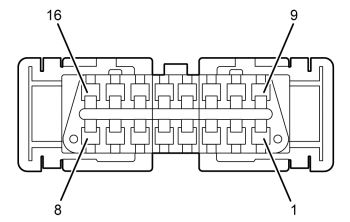
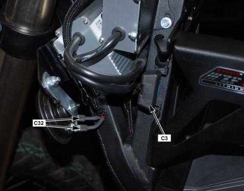
C3 Data Link Connector Face View |
||
|
18502
|
||
|
Connector Part Information |
|
|
|
Pin |
Wire Color |
Function |
| 1-3 | — | Not Used |
| 4 | BLK/BLU | 12 Volt Ground |
| 5 | ORN/BLK | Diagnostic Ground |
| 6 | WHT | CAN 1 High |
| 7 | — | Not Used |
| 8 | RED/BLK | U-Art Tx |
| 9 | GRY/BLK | U-ART Rx |
| 10 | — | Not Used |
| 11 | BLK | CAN 1 Ground |
| 12 | RED/ORN | Diagnostic 3.3 Volts |
| 13 | — | Not Used |
| 14 | BLU | CAN 1 Low |
| 15-16 | — | Not Used |
| Left Side of the Frame, Between the Horn and the Front Power Pack |
|
COM1459
Loading image...

|
Version 1
|
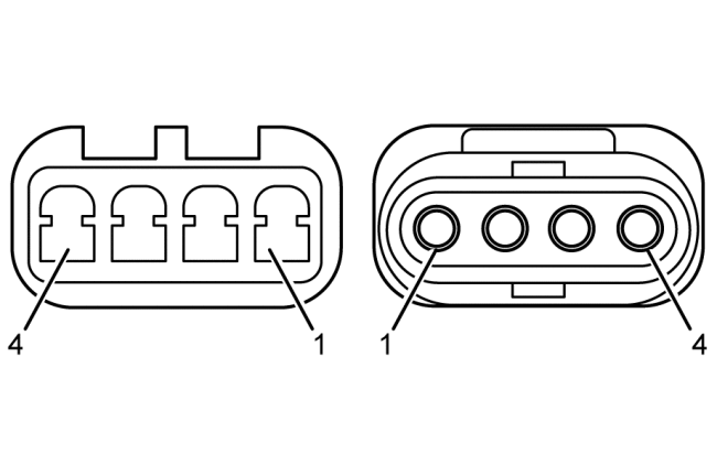
17841
Loading image...

|
|||||
| Connector Part Information |
|
Connector Part Information |
|
||
| Pin | Wire Color | Function | Pin | Wire Color | Function |
| 1 | — | Not Used |
1 |
— |
Not Used |
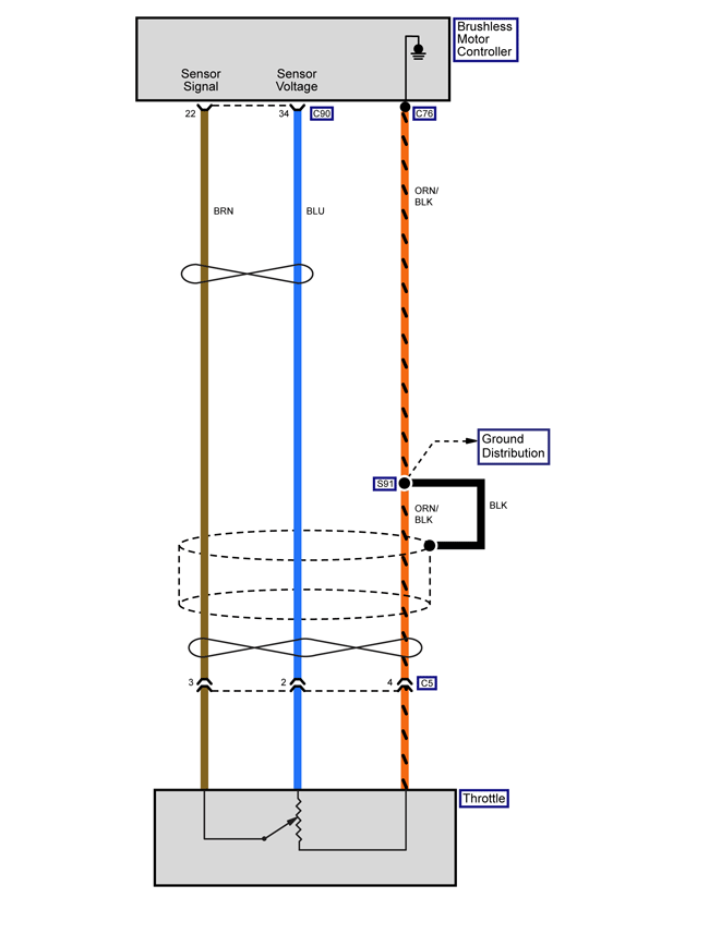
| 2 | BLU | Throttle Sensor Voltage |
2 |
— |
Throttle Sensor Voltage |
| 3 | BRN | Throttle Sensor Signal |
3 |
— |
Throttle Sensor Signal |
| 4 | ORN/BLK | Ground to Brushless Motor Controller |
4 |
— |
Ground to Brushless Motor Controller |
| Right Side of the Frame, Above the Power Pack Chargers |
|
COM1460
Loading image...

|
Version 1
|
C7 DC/DC Converter Fuse Connector Face View |
||
|
con0770
|
||
|
Connector Part Information |
|
|
|
Pin |
Wire Color |
Function |
| 1 | ORN | Low Voltage (+) Input |
| 2 | ORN/BLU | Low Voltage (+) Output |
| Below the Front Power Pack, Inside the Harness Cover |
|
COM1472
Loading image...

|
Version 1
|
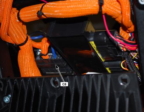
C8 DC/DC Converter Connector Face View |
||
|
18513
|
||
|
Connector Part Information |
|
|
|
Pin |
Wire Color |
Function |
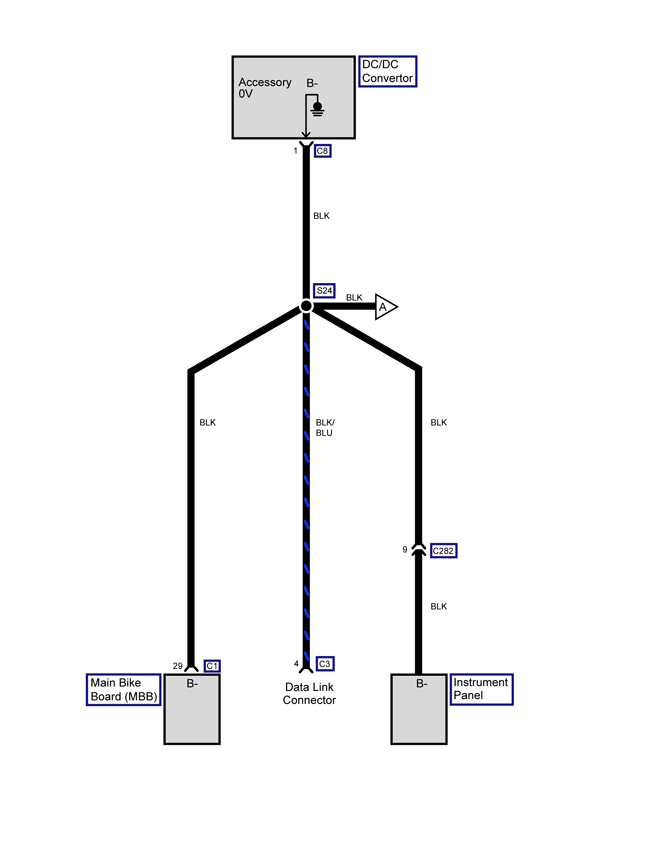
| 1 | BLK | Accessory 0 Volts |
| 2 | BLU | Accessory 12 Volts |
| 3 | ORN/BLK | Negative Input Voltage |
| 4 | ORN/BLU | Positive Input Voltage |
| 5 | ORN/RED | Converter Control |
| Right Front of the Frame, Under the Front Power Pack |
|
COM1473
Loading image...

|
Version 1
|
18512
Loading image...

|
|||||||
| Connector Part Information |
|
Connector Part Information |
|
||||
| Pin | Wire Color | Function | Pin | Wire Color | Function | ||
| 1 | BLU | 5 Volts | 1 | RED | 5 Volts | ||
| 2 | BLK | Battery Negative | 2 | ORN/BLK | Battery Negative | ||
| 3 | PNK | Kickstand Switch IN Signal | 3 | YEL/BLK | Kickstand Switch IN Signal | ||
| Left Side of the Frame, Next to the Brushless Motor Controller |
|
COM1461
Loading image...

|
Version 1
|
19328
Loading image...

|
|||||
| Connector Part Information |
|
Connector Part Information |
|
||
| Pin | Wire Color | Function | Pin | Wire Color | Function |
| A | WHT | Sine Digital Input | A | BLU | Sine Digital Input |
| B | BLU | Cosine Input | B | WHT | Cosine Input |
| C | BLK | Encoder Power Supply (–) | C | BLK | Encoder Power Supply (–) |
| D | — | Not Used | D | — | Not Used |
| E | RED | Encoder Power Supply (+) | E | RED | Encoder Power Supply (+) |
| F | GRN | Shield | F | — | Shield |
| G | YEL | Motor Controller Ground | G | ORN/BLK | Motor Controller Ground |
| H | YEL | Temperature Sensor Input | H | WHT | Temperature Sensor Input |
| Right Side of the Frame, Next to the Brushless Motor Controller |
|
COM1462
Loading image...

|
Version 1
|
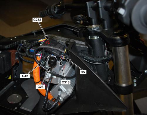
C26 Accessory Power Port Connector Face View |
||
|
CON0759
|
||
|
Connector Part Information |
|
|
|
Pin |
Wire Color |
Function |
| 1 | BLU | Fuse 2 Voltage |
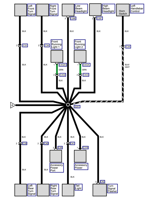
| 2 | BLK | Ground, Accessory 0 V |
| Right Side of the Frame, Above the Power Pack Chargers |
|
com1460
Loading image...

|
Version 1
|
C32 Horn Connector Face View |
||
|
con0758
|
||
|
Connector Part Information |
|
|
|
Pin |
Wire Color |
Function |
|
1 |
BLK/YEL |
Horn Ground Control |
|
C32 Horn Connector Face View |
||
|
con0758
|
||
|
Connector Part Information |
|
|
|
Pin |
Wire Color |
Function |
|
2 |
BLU/BLK |
Horn Supply Voltage |
| Left Front Side of the Frame |
|
com1459
Loading image...

|
Version 1
|
19226
Loading image...

|
|||||
| Connector Part Information |
|
Connector Part Information |
|
||
| Pin | Wire Color | Function | Pin | Wire Color | Function |
| 1 | WHT | Left Front Turn Signal Voltage | 1 | GRN | Left Front Turn Signal Voltage |
|
19226
Loading image...

|
|||||
| Connector Part Information |
|
Connector Part Information |
|
||
| Pin | Wire Color | Function | Pin | Wire Color | Function |
| 2 | BLK | Left Front Turn Signal Ground | 2 | BLK | Left Front Turn Signal Ground |
| Under the Instrument Panel, Behind the Headlight |
|
com1484
Loading image...

|
Version 1
|
19226
Loading image...

|
|||||
| Connector Part Information |
|
Connector Part Information |
|
||
| Pin | Wire Color | Function | Pin | Wire Color | Function |
| 1 | RED | Right Front Turn Signal Voltage | 1 | GRY | Right Front Turn Signal Voltage |
|
19226
Loading image...

|
|||||
| Connector Part Information |
|
Connector Part Information |
|
||
| Pin | Wire Color | Function | Pin | Wire Color | Function |
| 2 | BLK | Right Front Turn Signal Ground | 2 | BLK | Right Front Turn Signal Ground |
| Under the Instrument Panel, Behind the Headlight |
|
com1457
Loading image...

|
Version 1
|
C35
Loading image...

|
|||||
| Connector Part Information |
|
Connector Part Information |
|
||
| Pin | Wire Color | Function | Pin | Wire Color | Function |
| 1 | — | Not Used | 1 | — | Not Used |
| 2 | BRN | High Beam Input (Flash to Pass) | 2 | BRN | High Beam Input (Flash to Pass) |
| 3 | RED/YEL | Headlamp Low Beam Voltage | 3 | RED/YEL | Headlamp Low Beam Voltage |
| 4 | RED/BLK | Headlamp High Beam Voltage | 4 | RED/BLK | Headlamp High Beam Voltage |
| 5 | BLU/YEL | Headlamp Switch Voltage | 5 | BLU/YEL | Headlamp Switch Voltage |
| 6 | BLK/YEL | Horn Voltage | 6 | BLK/YEL | Horn Voltage |
| 7 | BLK/WHT | Horn Switch Ground | 7 | BLK | Horn Switch Ground |
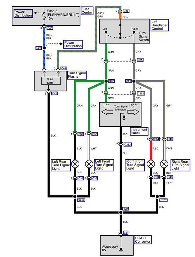
| 8 | GRY | Right Turn Signal Lamp Voltage | 8 | GRY | Right Turn Signal Lamp Voltage |
| 9 | GRY/GRN | Turn Signal | 9 | ORN | Turn Signal |
| 10 | GRN | Left Turn Signal Lamp Voltage | 10 | GRN | Left Turn Signal Lamp Voltage |
| Under the Instrument Panel, Behind the Headlight |
|
com1457
Loading image...

|
Version 1
|
19227
Loading image...

|
|||||
| Connector Part Information |
|
Connector Part Information |
|
||
| Pin | Wire Color | Function | Pin | Wire Color | Function |
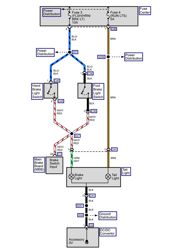
| 1 | BLU/BLK | Foot Brake Switch Supply Voltage | 1 | BLK | Foot Brake Switch Supply Voltage |
| 2 | WHT/RED | Foot Brake Switch Signal | 2 | BLK | Foot Brake Switch Signal |
| On the Right Side of the Frame, Behind the Power Pack |
|
com1463
Loading image...

|
Version 1
|
19226
Loading image...

|
|||||
| Connector Part Information |
|
Connector Part Information |
|
||
| Pin | Wire Color | Function | Pin | Wire Color | Function |
| 1 | RED | Left Rear Turn Signal Voltage | 1 | GRN | Left Rear Turn Signal Voltage |
|
19226
Loading image...

|
|||||
| Connector Part Information |
|
Connector Part Information |
|
||
| Pin | Wire Color | Function | Pin | Wire Color | Function |
| 2 | BLK | Left Rear Turn Signal Ground | 2 | BLK | Left Rear Turn Signal Ground |
| Above the Rear Fender |
|
com1464
Loading image...

|
Version 1
|
19226
Loading image...

|
|||||
| Connector Part Information |
|
Connector Part Information |
|
||
| Pin | Wire Color | Function | Pin | Wire Color | Function |
| 1 | WHT | Right Rear Turn Signal Voltage | 1 | GRY | Right Rear Turn Signal Voltage |
|
19226
Loading image...

|
|||||
| Connector Part Information |
|
Connector Part Information |
|
||
| Pin | Wire Color | Function | Pin | Wire Color | Function |
| 2 | BLK | Right Rear Turn Signal Ground | 2 | BLK | Right Rear Turn Signal Ground |
| Above the Rear Fender |
|
com1464
Loading image...

|
Version 1
|
17856
Loading image...

|
|||||
| Connector Part Information |
|
Connector Part Information |
|
||
| Pin | Wire Color | Function | Pin | Wire Color | Function |
| 1 | WHT/RED | Tail Light Ground | 1 | GRN/WHT | Tail Light Ground |
| 2 | BLK | Running Light Supply Ground | 2 | BLK | Running Light Supply Ground |
| 3 | BRN | Brake Light Supply Voltage | 3 | BRN | Brake Light Supply Voltage |
| Above the Rear Fender |
|
com1464
Loading image...

|
Version 1
|
C42 Turn Signal Flasher Connector Face View |
||
|
19225
|
||
|
Connector Part Information |
|
|
|
Pin |
Wire Color |
Function |
| 1 | BLU/BLK | Turn Signal Flasher Voltage |
| 2 | GRY/GRN | Turn Signal Lamp Control |
| 3 | BLK | Ground |
| Right Side of the Frame, Above the Power Pack Charger |
|
com1460
Loading image...

|
Version 1
|
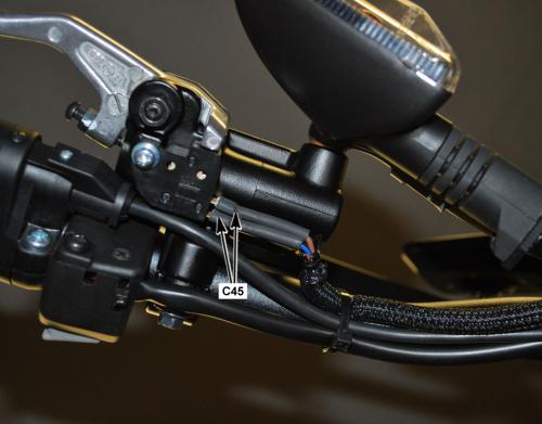
C45 Hand Brake Switch Connector Face View |
|||
|
con0758
Loading image...

|
|||
|
Connector Part Information |
|
||
| Pin | Wire Color | Function | |
| 1 | BLU/BLK |
Hand Brake Switch Supply Voltage |
|
|
C45 Hand Brake Switch Connector Face View |
|||
|
con0758
Loading image...

|
|||
|
Connector Part Information |
|
||
| Pin | Wire Color | Function | |
| 2 | WHT/RED |
Hand Brake Switch Signal |
|
| Right Side of the Handlebar, Under the Master Cylinder |
|
com1465
Loading image...

|
Version 1
|
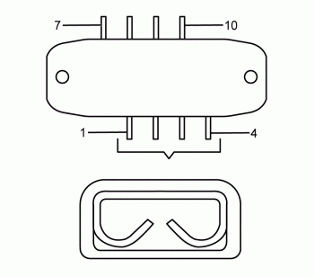
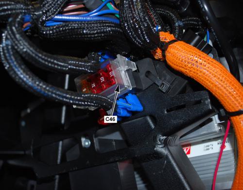
C46 Fuse Center Connector Bottom View |
||
|
con0757
|
||
|
Connector Part Information |
|
|
|
Pin |
Wire Color |
Function |
|
1 |
BLU |
Fuse 4 Supply Voltage |
|
2 |
BLU |
Fuse 3 Supply Voltage |
|
3 |
BLU |
Fuse 2 Supply Voltage |
|
4 |
BLU |
Fuse 1 Supply Voltage |
|
7 |
BRN |
Voltage to Splice S299 |
|
8 |
BLU/BLK |
Voltage to Splice S27 • Horn • Turn Signal Flasher • Brake Switches |
|
9 |
BLU |
Accessory Power Port |
|
10 |
BLU/YEL |
Voltage to Splice S25 Headlight Switch |
| Under the Front Panels, In Front of the Power Pack |
|
com1456
Loading image...

|
Version 1
|
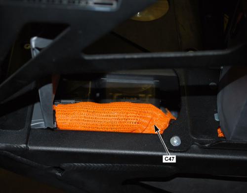
C47 Main Bike Board (MBB) Fuse Connector Face View |
|||
|
con0770
Loading image...

|
|||
|
Connector Part Information |
|
||
| Pin | Wire Color | Function | |
| 1 | ORN |
Low Voltage (+) Input |
|
| 2 | ORN/BRN |
Low Voltage (+) Output |
|
| Below the Front Power Pack, Across From the MBB, Inside the Harness Cover |
|
com1483
Loading image...

|
Version 1
|
C50 Quick Charge Connector Face View |
||
|
con0761
|
||
|
Connector Part Information |
|
|
|
Pin |
Wire Color |
Function |
|
1 |
BLK |
Fused Battery Positive (+) |
|
2 |
BLK |
Battery Negative (-) |
|
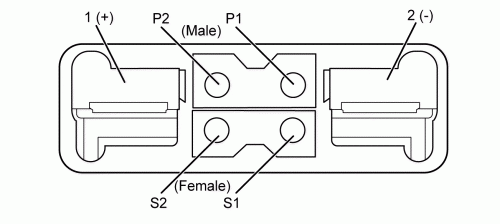
P1-P2 |
— |
Not Used |
|
S1 |
WHT/BRN |
Charger Enable 1 |
|
S2 |
WHT/BLK |
Charger Enable 0 |
| Right Side of the Frame, Between the Brushless Motor Controller and the Motor |
|
com1462
Loading image...

|
Version 1
|
C57 Charger Control Unit (CCU) Connector Face View |
||
|
con0748
|
||
|
Connector Part Information |
|
|
|
Pin |
Wire Color |
Function |
|
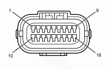
1-3 |
— |
Not Used |
|
4 |
BLK |
CAN Ground |
|
5 |
RED |
CAN 5 Volts |
|
6 |
BLU |
CAN 2 Low |
|
7 |
WHT |
CAN 2 High |
|
8-10 |
— |
Not Used |
|
11 |
ORN/GRN |
Charger Attached Signal |
|
12 |
WHT/BLK |
Charger Enable |
|
13 |
ORN/BLK |
Charger Ground |
|
14-18 |
— |
Not Used |
| Front of the Frame, Under the Power Pack Chargers |
|
com1466
Loading image...

|
Version 1
|
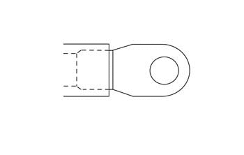
C74 Brushless Motor Controller Connector Face View |
||
|
con0051
Loading image...

|
||
|
Connector Part Information |
|
|
|
Pin |
Wire Color |
Function |
|
— |
BLK (Orange Sleeve Over Cable) |
Positive (+) Voltage |
| Front of the Frame, Below the Front Power Pack |
|
com1467
Loading image...

|
Version 1
|
C76 Brushless Motor Controller Connector Face View |
||
|
con0051
Loading image...


|
||
|
Connector Part Information |
|
|
|
Pin |
Wire Color |
Function |
|
— |
BLK (Orange Sleeve Over Cable) |
Negative (-) Ground |
| Front of the Frame, Below the Front Power Pack |
|
com1467
Loading image...

|
Version 1
|
C74 Brushless Motor Controller Connector Face View |
||
|
con0051
Loading image...


|
||
|
Connector Part Information |
|
|
|
Pin |
Wire Color |
Function |
|
— |
BLK (Orange Sleeve Over Cable) |
Positive (+) Voltage |
| Front of the Frame, Below the Front Power Pack |
|
com1467
Loading image...

|
Version 1
|
C76 Brushless Motor Controller Connector Face View |
||
|
con0051
Loading image...


|
||
|
Connector Part Information |
|
|
|
Pin |
Wire Color |
Function |
|
— |
BLK (Orange Sleeve Over Cable) |
Negative (-) Ground |
| Front of the Frame, Below the Front Power Pack |
|
com1467
Loading image...

|
Version 1
|
C79 Brushless Motor Controller Connector Face View |
||
|
con0050
|
||
|
Connector Part Information |
|
|
|
Pin |
Wire Color |
Function |
|
— |
GRN/YEL |
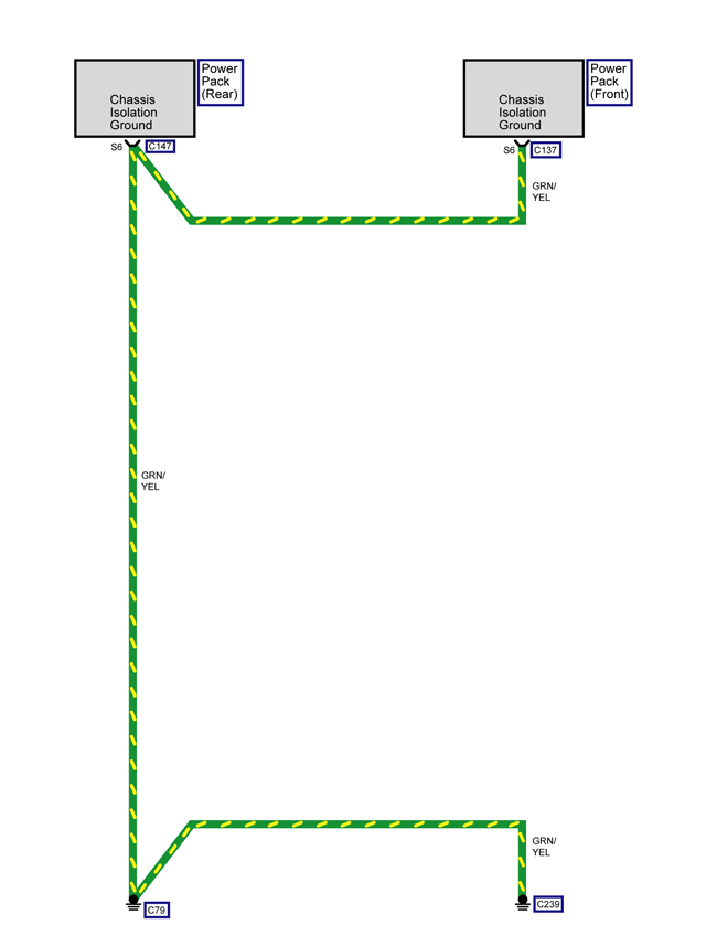
Ground (C147 and C239) |
| Right Side of the Frame, Behind the Fuse Center |
|
com1469
Loading image...

|
Version 1
|
C90 Brushless Motor Controller Connector Face View |
||
|
19332
|
||
|
Connector Part Information |
|
|
|
Pin |
Wire Color |
Function |
| 1 | ORN/RED | Voltage From Key Switch |
| 2 | BLU | CAN Termination |
| 3-5 | — | Not Used |
| 6 | ORN/RED | Voltage From Key Switch |
| 7-14 | — | Not Used |
| 15 | BLK | Encoder Power Supply (–) |
| 16 | WHT | CAN High |
| 17 | — | Not Used |
| 18 | ORN/GRY | Digital Input 1 |
| 19 | ORN/BLU | Digital Input 3 |
| 20 | — | Not Used |
| 21 | BLU | Digital Input 8 |
| 22 | BRN | Throttle Sensor Signal |
| 23 | — | Not Used |
| 24 | BLU | CAN Low |
| 25 | — | Not Used |
| 26 | RED | Encoder Power Supply (+) |
| 27 | BLU | CAN Low |
| 28 | YEL/RED | CAN Power Supply (+) |
| 29-30 | — | Not Used |
| 31 | ORN/YEL | Digital Input 4 |
| 32 | ORN/VIO | Digital Input 7 |
| 33 | WHT | Temperature Sensor Input |
| 34 | BLU | Throttle Sensor Voltage |
| 35 | WHT | COSINE Input |
| Right Side of the Frame, Next to the Brushless Motor Controller |
|
com1462
Loading image...

|
Version 1
|
C97 Brushless Motor Controller Connector View |
||
|
con0051
Loading image...


|
||
|
Connector Part Information |
|
|
|
Pin |
Wire Color |
Function |
| — | BLK (Orange Sleeve Over Cable) | Fused Negative (-) |
| Front of the Frame, Below the Front Power Pack |
|
com1467
Loading image...

|
Version 1
|
C113 Brushless Motor Controller Face View |
||
|
con0051
Loading image...


|
||
|
Connector Part Information |
|
|
|
Pin |
Wire Color |
Function |
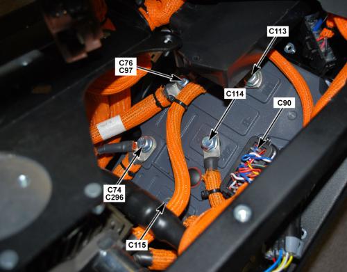
| — | BLK (Orange Sleeve Over Cable) | M1 Going to the Motor |
| Front of the Frame, Below the Front Power Pack |
|
com1467
Loading image...

|
Version 1
|
C114 Brushless Motor Connector Face View |
||
|
con0051
Loading image...


|
||
|
Connector Part Information |
|
|
|
Pin |
Wire Color |
Function |
| — | BLK (Orange Sleeve Over Cable) | Going to the Motor |
| Front of the Frame, Below the Front Power Pack |
|
com1467
Loading image...

|
Version 1
|
C115 Brushless Motor Connector Face View |
||
|
con0051
Loading image...


|
||
|
Connector Part Information |
|
|
|
Pin |
Wire Color |
Function |
| — | BLK (Orange Sleeve Over Cable) | Going to the Motor |
| Front of the Frame, Below the Front Power Pack |
|
com1467
Loading image...

|
Version 1
|
C137 Power Pack (Front) Signal Connector Face View |
||
|
con0766
|
||
|
Connector Part Information |
|
|
|
Pin |
Wire Color |
Function |
| P1 | ORN | Low Power B+ |
| P2 | RED | CAN 5 Volts |
| P3 | — | Not Used |
| P4 | YEL/GRY | 12 Volt Output |
| P5 | WHT | CAN High |
| P6 | — | Not Used |
| P7 | GRY/BRN | Node ID 1 |
| P8 | GRY/BRN | Ground |
| S1 | BRN | System ON Reference |
| S2 | BLK | CAN Ground |
| S3 | BRN/WHT | System ON |
| S4 | BLU | CAN Low |
| S5 | PNK | Loopback Output |
| S6 | GRN/YEL | Chassis Ground |
| S7 | PNK | Loopback Return |
| S8 | BLK/WHT | Throttle Enable |
| Center of the Frame, Between the Power Packs |
|
com1468
Loading image...

|
Version 1
|
C138 Front Power Pack Connector Face View |
||
|
con0767
|
||
|
Connector Part Information |
|
|
|
Pin |
Wire Color |
Function |
| 1 | BLK | Battery Positive (+) |
| 2 | BLK | Battery Positive (-) |
| Center of the Frame, Between the Power Packs |
|
com1468
Loading image...

|
Version 1
|
C147 Power Pack (Rear) Signal Connector Face View |
||
|
con0766
|
||
|
Connector Part Information |
|
|
|
Pin |
Wire Color |
Function |
| P1 | ORN ORN ORN |
Low Power B+ |
| P2 | RED RED |
CAN 5 Volts |
| P3 | — | Not Used |
| P4 | YEL/GRY YEL/GRY |
12 Volt Output |
| P5 | WHT WHT |
CAN High |
| P6 | GRY/BLK | Node ID 0 |
| P7 | GRY/BLK | Node ID 1 |
| P8 | GRY/BLK GRY/BLK |
Ground |
| S1 | BRN BRN |
System ON Reference |
| S2 | BLK BLK |
CAN Ground |
| S3 | BRN/WHT BRN/WHT |
System ON |
| S4 | BLU BLU |
CAN Low |
| S5 | PNK | Loopback Output |
| S6 | GRN/YEL GRN/YEL |
Chassis Ground to C79 |
| S7 | PNK | Loopback Input |
| S8 | BLK/WHT BLK/WHT |
Throttle Enable MBB and |
| Center of the Frame, Between the Power Packs |
|
com1468
Loading image...

|
Version 1
|
C148 Rear Power Pack Connector Face View |
||
|
con0767
|
||
|
Connector Part Information |
|
|
|
Pin |
Wire Color |
Function |
| 1 | BLK | Battery Positive (+) |
| 2 | BLK | Battery Positive (-) |
| Center of the Frame, Between the Power Packs |
|
com1468
Loading image...

|
Version 1
|
C203 Charger Control Unit (CCU) Connector Face View |
||
|
con0769
|
||
|
Connector Part Information |
|
|
|
Pin |
Wire Color |
Function |
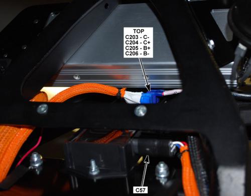
| — | BLK | C- |
| Front of the Frame, Under the Power Pack Chargers |
|
com1466
|
Version 1
|
C204 Charger Control Unit (CCU) Connector Face View |
||
|
con0769
|
||
|
Connector Part Information |
|
|
|
Pin |
Wire Color |
Function |
| — | RED | C+ |
| Front of the Frame, Under the Power Pack Chargers |
|
com1466
|
Version 1
|
C205 Charger Control Unit (CCU) Connector Face View |
||
|
con0769
|
||
|
Connector Part Information |
|
|
|
Pin |
Wire Color |
Function |
| — | ORN | B+ |
| Front of the Frame, Under the Power Pack Chargers |
|
com1466
Loading image...

|
Version 1
|
C206 Charger Control Unit (CCU) Connector Face View |
||
|
con0769
|
||
|
Connector Part Information |
|
|
|
Pin |
Wire Color |
Function |
| — | ORN/BLK | B+ |
| Front of the Frame, Under the Power Pack Chargers |
|
com1466
Loading image...

|
Version 1
|
C207 Charger Control Unit (CCU) Fuse Connector Face View |
||
|
con0770
|
||
|
Connector Part Information |
|
|
|
Pin |
Wire Color |
Function |
| 1 | ORN | Low Voltage (+) Input |
| 2 | ORN | Low Voltage (+) Output |
| Right Front of Frame, Under Front Power Pack, Inside the Harness |
|
com1475
Loading image...

|
Version 1
|
C239 Equipment Ground (Frame) Face View |
||
|
con0050
|
||
|
Connector Part Information |
|
|
|
Pin |
Wire Color |
Function |
| — | GRN/YEL | Ground |
| Under the Instrument Panel, Behind the Headlight |
|
com1457
Loading image...

|
Version 1
|
18510
Loading image...

|
|||||||
| Connector Part Information |
|
Connector Part Information |
|
||||
| Pin | Wire Color | Function | Pin | Wire Color | Function | ||
| 1 | — | Not Used | 1 | LT BLU | Not Used | ||
| 2 | — | Not Used | 2 | BRN | Not Used | ||
| 3 | YEL/GRY | Key Switch Ground | 3 | RED | Key Switch Ground | ||
| 4 | YEL/GRN | Key Switch Signal | 4 | RED/BLK | Key Switch Signal | ||
| Right Side of the Frame, Above the Power Pack Chargers |
|
com1469
Loading image...

|
Version 1
|
con0753
Loading image...

|
|||||||
| Connector Part Information |
|
Connector Part Information |
|
||||
| Pin | Wire Color | Function | Pin | Wire Color | Function | ||
| 1 | BLU/WHT | Start Switch Signal | 1 | BLK | Start Switch Signal | ||
| 2 | RED | Switch 5 Volts | 2 | BLU/WHT | Switch 5 Volts | ||
| 3 | RED | Motor Stop Switch Output 5 Volts | 3 | RED/WHT | Motor Stop Switch Output 5 Volts | ||
| 4 | WHT | Motor Stop Switch Input | 4 | RED/WHT | Motor Stop Switch Input | ||
| Under the Instrument Panel, Behind the Headlight |
|
com1457
Loading image...

|
Version 1
|
CON0752
Loading image...

|
|||||||
| Connector Part Information |
|
Connector Part Information |
|
||||
| Pin | Wire Color | Function | Pin | Wire Color | Function | ||
| 1 | YEL/BLK | Warning Light Control (red) | 1 | YEL/BLK | Warning Light Control (red) | ||
| 2 | YEL | Temperature Light Control (amber) | 2 | YEL | Temperature Light Control (amber) | ||
| 3 | RED/WHT | Armed Light Control (green) | 3 | GRN | Armed Light Control (green) | ||
| 4 | VIO | Charge LED Light Control (green) | 4 | WHT/BLK | Charge LED Light Control (green) | ||
| 5 | — | Not Used | 5 | BLU | Not Used | ||
| 6 | RED/BLK | High Beam Indicator Control (blue) | 6 | BRN/BLK | High Beam Indicator Control (blue) | ||
| 7 | GRN | Left Turn Indicator Control (green) | 7 | GRN | Left Turn Indicator Control (green) | ||
| 8 | GRY | Right Turn Indicator Control (green) | 8 | GRY | Right Turn Indicator Control (green) | ||
| 9 | BLK | Ground 12 Volt | 9 | BLK | Ground 12 Volt | ||
| 10 | WHT/BLK | State of Charge Control (5 Volt) | 10 | PNK | State of Charge Control (5 Volt) | ||
| 11 | WHT | CAN 2 High | 11 | WHT | CAN 2 High | ||
| 12 | BLU | CAN 2 Low | 12 | BLU | CAN 2 Low | ||
| 13 | ORN/BLK | CAN 2 5 Volts | 13 | ORN/BLK | CAN 2 5 Volts | ||
| 14 | — | Not Used | 14 | GRY | Not Used | ||
| 15 | — | Not Used | 15 | ORN | Not Used | ||
| 16 | BRN | 12 Volt Feed | 16 | BRN | 12 Volt Feed | ||
| 17-20 | — | Not Used | 17-20 | — | Not Used | ||
| Right Side of the Frame, Above the Power Pack Chargers |
|
com1460
Loading image...

|
Version 1
|
C286 Low Beam Headlight Connector Face View |
|||
|
con0758
Loading image...

|
|||
|
Connector Part Information |
|
||
| Pin | Wire Color | Function | |
| 1 | RED/YEL |
Low Beam Control |
|
|
con0758
Loading image...

|
|||
|
Connector Part Information |
|
||
| Pin | Wire Color | Function | |
| 2 | BLK |
Low Beam Ground |
|
| Behind the Headlight Assembly |
|
com1470
Loading image...

|
Version 1
|
C287 High Beam Headlight Connector Face View |
|||
|
con0758
Loading image...

|
|||
|
Connector Part Information |
|
||
| Pin | Wire Color | Function | |
| 1 | RED/BLU |
High Beam Control |
|
|
con0758
Loading image...

|
|||
|
Connector Part Information |
|
||
| Pin | Wire Color | Function | |
| 2 | BLK |
High Beam Ground |
|
| Behind the Headlight Assembly |
|
com1470
Loading image...

|
Version 1
|
C296 Brushless Motor Controller Connector Face View |
|||
|
con0051
Loading image...


|
|||
|
Connector Part Information |
|
||
| Pin | Wire Color | Function | |
| — | BLK (Orange Sleeve Over Cable |
Positive (+) |
|
| Front of the Frame, Below the Front Power Pack |
|
com1467
Loading image...

|
Version 1
|
con0762
Loading image...

|
|||||||
| Connector Part Information |
|
Connector Part Information |
|
||||
| Pin | Wire Color | Function | Pin | Wire Color | Function | ||
| 1 | BLK | Fused Battery Positive Voltage (+) | 1 | BLK | Fused Battery Positive Voltage (+) | ||
| 2 | BLK | Battery Negative (-) | 2 | BLK | Battery Negative (-) | ||
| Behind the Right Side of the Power Pack, Next to the Foot Brake Pedal |
|
com1450
Loading image...

|
Version 1
|
C318 12 Volt Accessory Connector Face View |
||
|
con0749
|
||
|
Connector Part Information |
|
|
|
Pin |
Wire Color |
Function |
| 1 | BLK | Ground, Accessory 0 V |
| 2 | BLU | Fuse 2 Voltage |
| Right Side of the Frame, Above the Power Pack Chargers |
|
com1460
Loading image...

|
Version 1
|
con0756
Loading image...

|
|||||||
| Connector Part Information |
|
Connector Part Information |
|
||||
| Pin | Wire Color | Function | Pin | Wire Color | Function | ||
| 1 | BRN | Running Light Control | 1 | BRN | Running Light Control | ||
|
con0756
Loading image...

|
|||||||
| Connector Part Information |
|
Connector Part Information |
|
||||
| Pin | Wire Color | Function | Pin | Wire Color | Function | ||
| 2 | BLK | Running Light Ground | 2 | GRN | Running Light Ground | ||
| Behind the Headlight Assembly |
|
com1470
Loading image...

|
Version 1
|
C432A Front Running Light Connector Face View |
||
|
18077
|
||
|
Connector Part Information |
|
|
|
Pin |
Wire Color |
Function |
| 1 | GRN | Running Lamp Ground |
| 2 | BRN | Running Lamp Supply Voltage |
| Bottom of the Headlight |
|
com1485
Loading image...

|
Version 1
|
con0756
Loading image...

|
|||||||
| Connector Part Information |
|
Connector Part Information |
|
||||
| Pin | Wire Color | Function | Pin | Wire Color | Function | ||
| 1 | BRN | Running Light Control | 1 | BRN | Running Light Control | ||
|
con0756
Loading image...

|
|||||||
| Connector Part Information |
|
Connector Part Information |
|
||||
| Pin | Wire Color | Function | Pin | Wire Color | Function | ||
| 2 | BLK | Running Light Ground | 2 | GRN | Running Light Ground | ||
| Behind the Headlight Assembly |
|
com1470
Loading image...

|
Version 1
|
C287 High Beam Headlight Connector Face View |
|||
|
con0758
Loading image...

|
|||
|
Connector Part Information |
|
||
| Pin | Wire Color | Function | |
| 1 | RED/BLU |
High Beam Control |
|
|
con0758
Loading image...

|
|||
|
Connector Part Information |
|
||
| Pin | Wire Color | Function | |
| 2 | BLK |
High Beam Ground |
|
| Behind the Headlight Assembly |
|
com1470
Loading image...

|
Version 1
|
C296 Brushless Motor Controller Connector Face View |
|||
|
con0051
Loading image...


|
|||
|
Connector Part Information |
|
||
| Pin | Wire Color | Function | |
| — | BLK (Orange Sleeve Over Cable |
Positive (+) |
|
| Front of the Frame, Below the Front Power Pack |
|
com1467
Loading image...

|
Version 1
|
con0762
Loading image...

|
|||||||
| Connector Part Information |
|
Connector Part Information |
|
||||
| Pin | Wire Color | Function | Pin | Wire Color | Function | ||
| 1 | BLK | Fused Battery Positive Voltage (+) | 1 | BLK | Fused Battery Positive Voltage (+) | ||
| 2 | BLK | Battery Negative (-) | 2 | BLK | Battery Negative (-) | ||
| Behind the Right Side of the Power Pack, Next to the Foot Brake Pedal |
|
com1450
Loading image...

|
Version 1
|
C318 12 Volt Accessory Connector Face View |
||
|
con0749
|
||
|
Connector Part Information |
|
|
|
Pin |
Wire Color |
Function |
| 1 | BLK | Ground, Accessory 0 V |
| 2 | BLU | Fuse 2 Voltage |
| Right Side of the Frame, Above the Power Pack Chargers |
|
com1460
Loading image...

|
Version 1
|
con0756
Loading image...

|
|||||||
| Connector Part Information |
|
Connector Part Information |
|
||||
| Pin | Wire Color | Function | Pin | Wire Color | Function | ||
| 1 | BRN | Running Light Control | 1 | BRN | Running Light Control | ||
|
con0756
Loading image...

|
|||||||
| Connector Part Information |
|
Connector Part Information |
|
||||
| Pin | Wire Color | Function | Pin | Wire Color | Function | ||
| 2 | BLK | Running Light Ground | 2 | GRN | Running Light Ground | ||
| Behind the Headlight Assembly |
|
com1470
Loading image...

|
Version 1
|
C432A Front Running Light Connector Face View |
||
|
18077
|
||
|
Connector Part Information |
|
|
|
Pin |
Wire Color |
Function |
| 1 | GRN | Running Lamp Ground |
| 2 | BRN | Running Lamp Supply Voltage |
| Bottom of the Headlight |
|
com1485
Loading image...

|
Version 1
|
con0756
Loading image...

|
|||||||
| Connector Part Information |
|
Connector Part Information |
|
||||
| Pin | Wire Color | Function | Pin | Wire Color | Function | ||
| 1 | BRN | Running Light Control | 1 | BRN | Running Light Control | ||
|
con0756
Loading image...

|
|||||||
| Connector Part Information |
|
Connector Part Information |
|
||||
| Pin | Wire Color | Function | Pin | Wire Color | Function | ||
| 2 | BLK | Running Light Ground | 2 | GRN | Running Light Ground | ||
| Behind the Headlight Assembly |
|
com1470
Loading image...

|
Version 1
|
C433A Front Running Light Connector Face View |
||
|
18077
|
||
|
Connector Part Information |
|
|
|
Pin |
Wire Color |
Function |
| 1 | GRN | Running Lamp Ground |
| 2 | BRN | Running Lamp Supply Voltage |
| Bottom of the Headlight |
|
com1485
Loading image...

|
Version 1
|
D11 Inline Temperature Sensor |
||
|
Image Not Available
|
||
|
Pin |
Wire Color |
Function |
| 1 | BLK | Temperature Sensor 1 Input |
| 2 | BLK | Ground |
Photo Not Available
Version 1
|
D317 Charger Fuse Connector Face View |
||
|
con0051
Loading image...


|
||
|
Connector Part Information |
|
|
|
Pin |
Wire Color |
Function |
| 1 | BLK (Orange Sleeve Over Cable) | Positive (+) Output |
|
con0051
Loading image...


|
||
|
Connector Part Information |
|
|
|
Pin |
Wire Color |
Function |
| 2 | BLK (Orange Sleeve Over Cable) | Battery Positive (+) Input |
| Above the Brushless Motor Controller, In Front of the Motor |
|
com1461
Loading image...

|
Version 1
Right Side of the Frame, Under the Tank Bag/Power Tank

|
Joint |
Connector |
Pin |
Color |
Function |
|
Loading image...

|
C35 | 8 | GRY | Right Turn Signal Input |
|
Loading image...

|
C282 | 8 | GRY | Right Turn Signal Output |
|
Loading image...

|
C40 | 1 | GRY | Right Turn Signal Output |
|
Loading image...

|
C34 | 1 | GRY | Right Turn Signal Output |
Version 1
Right Side of the Frame, Under the Tank Bag/Power Tank

|
Joint |
Connector |
Pin |
Color |
Function |
|
Loading image...

|
C35 | 10 | GRN | Left Turn Signal Input |
|
Loading image...

|
C282 | 7 | GRN | Left Turn Signal Output |
|
Loading image...

|
C39 | 1 | GRN | Left Turn Signal Output |
|
Loading image...

|
C33 | 1 | GRN | Left Turn Signal Output |
Version 1
Left Side of the Frame, Next to the Fuse Center

|
Joint |
Connector |
Pin |
Color |
Function |
|
Loading image...

|
C8 | 2 | BLU | 12 Volt Input |
|
Loading image...

|
C46 | 1 | BLU | 12 Volt Output |
|
Loading image...

|
C46 | 2 | BLU | 12 Volt Output |
|
Loading image...

|
C46 | 3 | BLU | 12 Volt Output |
|
Loading image...

|
C46 | 4 | BLU | 12 Volt Output |
Version 1
Left Side of the Frame, Next to the Fuse Center

|
Joint |
Connector |
Pin |
Color |
Function |
|
Loading image...

|
C8 | 1 | BLK | 12 Volt Ground Input |
|
Loading image...

|
S257 | — | BLK | 12 Volt Ground Output |
|
Loading image...

|
C1 | 29 | BLK | 12 Volt Ground Output |
|
Loading image...

|
C282 | 9 | BLK | 12 Volt Ground Output |
|
Loading image...

|
C3 | 4 | BLK/BLU | 12 Volt Ground Output |
Version 1
Front of the Motorcycle, Under the Instrument Panel

|
Joint |
Connector |
Pin |
Color |
Function |
|
Loading image...

|
C46 | 10 | BLU/YEL | 12 Volt Input (fuse 1) |
|
Loading image...

|
C35 | 5 | BLU/YEL | High/Low Beam Headlight |
|
Loading image...

|
C35 | 2 | BRN | Flash to Pass |
Version 1
Front of the Motorcycle, Under the Instrument Panel

|
Joint |
Connector |
Pin |
Color |
Function |
|
Loading image...

|
C46 | 8 | BLU/BLK | 12 Volt Input (fuse 3) |
|
Loading image...

|
C38 | 1 | BLU/BLK | Foot Brake Light Switch |
|
Loading image...

|
C45 | 1 | BLU/BLK | Hand Brake Light Switch |
|
Loading image...

|
C42 | 1 | BLU/BLK | Turn Signal Flasher |
|
Loading image...

|
C32 | 2 | BLU/BLK | Horn |
Version 1
Left Side of the Frame, Next to the Fuse Center

|
Joint |
Connector |
Pin |
Color |
Function |
|
Loading image...

|
C35 | 4 | RED/BLK | Headlight Switch Output |
|
Loading image...

|
C287 | 1 | RED/BLK | Headlight Switch Output |
|
Loading image...

|
C282 | 6 | RED/BLK | I/P High Beam Indicator Control Input |
Version 1
Left Side of the Frame, Under the Seat

|
Joint |
Connector |
Pin |
Color |
Function |
|
Loading image...

|
C45 | 2 | WHT/RED | Hand Brake Light Switch Output |
|
Loading image...

|
C41 | 1 | WHT/RED | Brake Light Input |
|
Loading image...

|
C38 | 2 | WHT/RED | Foot Brake Light Switch Output |
|
Loading image...

|
C1 | 28 | WHT/RED | Brake Light Switch Input |
Version 1
Right Side of the Frame, Next to the Brushless Motor Controller

|
Joint |
Connector |
Pin |
Color |
Function |
|
Loading image...

|
C76 | 1 | ORN/BLK | Brushless Motor Controller (ground) |
|
Loading image...

|
C2 | 1 | ORN/BLK | Main Bike Board (MBB) |
|
Loading image...

|
C1 | 7 | ORN/BLK | Main Bike Board (MBB) |
|
Loading image...

|
C14 | G | ORN/BLK | Motor |
|
Loading image...

|
C5 | 4 | ORN/BLK | Throttle |
|
Loading image...

|
C8 | 3 | ORN/BLK | DC/DC Converter |
|
Loading image...

|
C50 | 2 | ORN/BLK | Quick Charger Connector |
Version 1
Below the Front Power Pack, In Front of the Motor
Photo Not Available
|
Joint |
Connector |
Pin |
Color |
Function |
|
Loading image...

|
C97 | — | BLK (Orange Sleeve Over Cable) | Brushless Motor Controller Negative (-) |
|
Loading image...

|
C138 | 2 | BLK (Orange Sleeve Over Cable) | Front Power Pack Negative (-) |
|
Loading image...

|
C148 | 2 | BLK (Orange Sleeve Over Cable) | Rear Power Pack Negative (-) |
Version 1
Right Side of the Frame, Under the Tank Bag/Power Tank

|
Joint |
Connector |
Pin |
Color |
Function |
|
Loading image...

|
S24 | - | BLK | 12 Volt Ground Input |
|
Loading image...

|
C40 | 2 | BLK | 12 Volt Ground Output |
|
Loading image...

|
C41 | 2 | BLK | 12 Volt Ground Output |
|
Loading image...

|
C433 | 2 | BLK | 12 Volt Ground Output |
|
Loading image...

|
C432 | 2 | BLK | 12 Volt Ground Output |
|
Loading image...

|
C286 | 2 | BLK | 12 Volt Ground Output |
|
Loading image...

|
C39 | 2 | BLK | 12 Volt Ground Output |
|
Loading image...

|
C287 | 2 | BLK | 12 Volt Ground Output |
|
Loading image...

|
C35 | 7 | BLK/WHT | 12 Volt Ground Output |
|
Loading image...

|
C33 | 2 | BLK | 12 Volt Ground Output |
|
Loading image...

|
C42 | 3 | BLK | 12 Volt Ground Output |
|
Loading image...

|
C34 | 2 | BLK | 12 Volt Ground Output |
|
Loading image...

|
C26 | 2 | BLK | 12 Volt Ground Output |
|
Loading image...

|
C32 | 2 | BLU/BLK | 12 Volt Ground Output |
Version 1
Below the Front Power Pack, In Front of the Motor

|
Joint |
Connector |
Pin |
Color |
Function |
|
Loading image...

|
C97 | — | BLK (Orange Sleeve Over Cable) | Brushless Motor Controller Positive (+) |
|
Loading image...

|
C138 | 1 | BLK (Orange Sleeve Over Cable) | Front Power Pack Positive (+) |
|
Loading image...

|
C148 | 1 | BLK (Orange Sleeve Over Cable) | Rear Power Pack Positive (+) |
Version 1
Right Side of the Frame, Under the Tank Bag/Power Tank

|
Joint |
Connector |
Pin |
Color |
Function |
|
Loading image...

|
C46 | 7 | BRN | Fuse 4 Output |
|
Loading image...

|
C41 | 3 | BRN | Tail Light 12 Volts |
|
Loading image...

|
C432 | 1 | BRN | Front Running Light 1 12 Volts |
|
Loading image...

|
C282 | 16 | BRN | Instrument Panel 12 Volts |
|
Loading image...

|
C433 | 1 | BRN | Front Running Light 2 12 Volts |
|
Loading image...

|
C1 | 30 | BRN | Main Bike Board (MBB) 12 Volts |
Version 1
Below the Front Power Pack, Across from the Main Bike Board

|
Joint |
Connector |
Pin |
Color |
Function |
|
Loading image...

|
C2 | 6 | WHT | Main Bike Board CAN High Output |
|
Loading image...

|
C57 | 7 | WHT | Charger Control Unit |
|
Loading image...

|
C282 | 11 | WHT | Instrument Panel |
Version 1
Below the Front Power Pack, Across from the Main Bike Board

|
Joint |
Connector |
Pin |
Color |
Function |
|
Loading image...

|
C2 | 7 | BLU | Main Bike Board CAN Low Output |
|
Loading image...

|
C57 | 6 | BLU | Charger Control Unit |
|
Loading image...

|
C282 | 12 | BLU | Instrument Panel |
Version 1
Caution: Always perform the High Voltage Disabling procedure prior to servicing any High Voltage component or connection. Proper procedures must be followed.
Failure to follow the procedures may result in serious injury or death.
• Always verify that the high voltage has been disabled before working on or around high voltage components, wires, cables, or harnesses.
• Remove all metal objects such as rings and watches.
• Always tighten the high voltage terminal fasteners to the specified torque. Insufficient or excessive torque will cause malfunctions or damage.
• After finishing work on the high voltage system and before turning the key ON.
o Verify high voltage system integrity and that all connectors and covers are installed.
o Verify that all tools or loose components have been removed.
Caution: Exposure to high voltage can cause shock, burns, and even death. The high voltage components on the motorcycle should only be serviced by technicians familiar with the circuit/system operation. Refer to System Description and Operation.
High voltage components are identified by labels. Do not remove, open, take apart, or modify these components. High voltage cable or wiring has orange covering. Do not probe, tamper with, cut, or modify high voltage cable or wiring.
Required Tools
PN 85-05665 Controller Discharge Tool

1. Review the High Voltage System Description and Operation.
2. Remove the key from the key switch.
3. Remove the fasteners in the upper rear corner of the right lower rubber cover.
4. Clean any dirt or debris away from the quick charge connector.
5. Plug the Controller Discharge Tool (1) into the quick charge connector, allow 30 seconds for the capacitors to discharge. Note: the bulb may or may not light up pending on the amount of strained voltage in the brushless motor controllers capacitors.

Version 1
| Torque settings for: Instrument Panel Replacement | |
| Item | Torque Setting |
| Instrument Panel Nuts | 4 N•m (36 lb in) |
| Axle Adjuster Jam Nut | 1.3 N•m (12 lb in) |
 Show Torque Table
Required Tools
• 3mm hex wrench
• 10mm wrench or socket
• Socket wrench
Fastener Torques
• Instrument panel nuts 4 N•m (36 lb in)
• Front fairing screws 1.3 N•m (12 lb in)
Removal Procedure
1. Remove the flyscreen.
2. Remove the right fairing panel.
3. Disconnect the instrument panel harness connector C282. Note the location of the zip ties for reassembly.
4. Remove and discard the zip ties.
5. Remove the 2 nuts (1) securing the instrument panel to the bracket, remove the instrument panel.

Installation Procedure
Notice: Refer to Fastener Notice in General Information
1. Install the 2 nuts (1) securing the instrument panel to the turn signal brackets.
Tighten
Instrument Panel nuts to 4 N•m (36 lb in)
2. Connect the instrument panel harness connector C282.
3. Turn the handlebar fully right and install new zip ties in the same location as removed.
4. Install the flyscreen. Ensure that ground C239 is between the flyscreen bolt and the bracket.
5. Install the right fairing panel.

Version 1
| Torque settings for: Main Chassis Harness Replacement | |
| Item | Torque Setting |
| Front Fender Bolts | 2 N•m (22 lb in) |
| Brushless Motor Controller Top Bracket Bolts | 11 N•m (8 lb ft) |
| Seat Bolts | 15 N•m (11 lb ft) |
| Brushless Motor Controller Bolt | 11 N•m (8 lb ft) |
| Front Fairing Screws | 1.3 N•m (12 lb in) |
 Show Torque Table
Caution: Always perform the High Voltage Disabling procedure prior to servicing any High Voltage component or connection. Proper procedures must be followed.
Required Tools
• 3mm hex wrench
• 5mm hex wrench
• 7mm socket
• 10mm socket
• Socket wrench
• 13mm wrench
• PN 85-05665 Controller Discharge Tool
Fastener Torques
• Brushless motor controller cable bolt 11 N•m (8 lb ft)
• Seat bolts 15 N•m (11 lb ft)
• Brushless motor controller upper bracket bolts 11 N•m (8 lb ft)
• Front fairing screws 1.3 N•m (12 lb in)
• Front fender bolts 2 N•m (22 lb in)
Removal Procedure

Caution: Refer to High Voltage Caution in General Information
Note routing and location of harness and zip tie.
1. Disable the High Voltage system. Refer to High Voltage Disabling.
2. Remove the power packs.
3. Remove the flyscreen.
4. Remove the seat.
5. Remove the rear fender.
6. Remove the front fender.
7. Remove the fairing assembly (FAIRING FRONT RIGHT POLYPROPOLENE BLACK, FAIRING FRONT LEFT POLYPROPOLENE BLACK, XMX FAIRING CENTER).
8. Remove the upper brushless motor controller bracket.
9. Remove the lower rubber side covers (XMX CONTROLLER COVER L, XMX CONTROLLER COVER R) .
10. Remove the screws securing the (1) securing the power pack connectors to the frame.
11. Remove the C137 and C147 (2) from the power pack connector body.

12. Disconnect C1 and C2 main bike board connectors.
13. Disconnect C10 kickstand switch connector.
14. Disconnect C57 charger control unit (CCU) connector.
15. Disconnect C205 and C206 charger control unit (CCU) connectors.
16. Remove the C3 data link connector fasteners.
17. Disconnect C8 DC/DC convertor connector.
18. Disconnect C14 motor harness connector.
19. Remove C76 ground eyelet from the brushless motor controller.
20. Disconnect the C90 controller connector.
21. Remove the C50 quick charge connector bracket.
22. Remove C74 positive eyelet from the brushless motor controller.
23. Remove the harness mounting bracket from the frame.
24. Remove the C79 ground eyelet from the frame.
25. Disconnect C274 key switch connector.
26. Disconnect C42 turn signal flasher connector.
27. Disconnect C5 throttle connector.
28. Disconnect C282 instrument panel connector.
29. Remove the headlight assembly.
30. Disconnect C275 right handlebar control connector.
31. Disconnect C33 right front turn signal connector.
32. Disconnect C34 left front turn signal connector.
33. Disconnect C35 left handlebar control connector.
34. Disconnect C32 horn connectors.
35. Disconnect C45 hand brake switch connector.
36. Remove the fuse center fasteners.
37. Disconnect C38 foot brake lamp switch connector.
38. Disconnect C39 left rear turn signal connector.
39. Disconnect C40 right rear turn signal connector.
40. Disconnect C41 tail light connector.
Note harness routing prior to removal, this will aid in reassembly of the harness to the motorcycle.
41. Release all main wiring harness zip ties and hold down brackets and remove the harness.
Installation Procedure

1. Layout the wiring harness in the same location as removed on the frame.
2. Connect C41 tail light connector.
3. Connect C40 right rear turn signal connector.
4. Connect C39 Left rear turn signal connector.
5. Connect C38 foot brake lamp switch connector.
6. Install the fuse center and fuse center fasteners.
7. Connect C45 hand brake switch connector.
8. Connect C32 horn connectors.
9. Connect C35 left handlebar control connector.
10. Connect C33 right front turn signal connector.
11. Connect C34 left front turn signal connector.
12. Install the headlight assembly.
13. Connect C274 key switch connector.
14. Connect C282 instrument panel connector.
15. Install the C79 ground eyelet from the frame.
16. Place the harness mounting bracket onto the frame and install the mounting bolt.
17. Connect C5 throttle connector.
18. Connect C42 turn signal flasher connector.
19. Connect C205 and C206 charger control unit (CCU) connectors.
20. Connect C8 DC/DC convertor connector.
21. Connect C14 motor harness connector.
Notice: Refer to Fastener Notice in General Information.
22. Install C76 ground eyelet onto the brushless motor controller and tighten the bolt.
Tighten
Brushless motor controller bolt to 11 N•m (8 lb ft)
23. Connect the C90 controller connector.
24. Install the C50 quick charge connector and bracket.
25. Install C74 positive eyelet onto the brushless motor controller and tighten the bolt.
Tighten
Brushless motor controller bolt to 11 N•m (8 lb ft)
26. Install the C3 data link connector and fasteners.
27. Connect C57 charger control unit (CCU) connector.
28. Connect C10 kickstand switch connector.
29. Connect C1 and C2 main bike board connectors.
30. Install the C137 and C147 (2) into the power pack connector body. Connector C147 is for the bottom connector and the C137 is for the top connector.
31. Install the power pack connector bolts (1) and cover.

32. Install zip ties in the same locations as removed.
33. Inspect harness routing to ensure that it is not in contact with any moving or sharp parts that could cause damage to the harness.
34. Install the upper brushless motor controller bracket.
35. Install the front fairing.
36. Install the front fender.
37. Install the rear fender.
38. Install the flyscreen. Ensure that ground C239 is between the flyscreen bolt and the bracket.
39. Install the lower rubber side covers.
40. Install the power packs.
41. Adjust the headlight. Refer to Headlight Adjustment.
Version 1
| Torque settings for: Power Pack Harness Replacement | |
| Item | Torque Setting |
| Brushless Motor Controller Cable Bolt | 11 N•m (8 lb ft) |
 Show Torque Table
Caution: Always perform the High Voltage Disabling procedure prior to servicing any High Voltage component or connection. Proper procedures must be followed.
Required Tools
• 3mm hex wrench
• 7mm socket
• Socket wrench
• 13mm wrench
• PN 85-05665 Controller Discharge Tool
Fastener Torques
• Brushless motor controller cable bolt 11 N•m (8 lb ft)
Removal Procedure

Caution: Refer to High Voltage Caution in General Information.
Note routing and location of harness and zip tie.
1. Disable the High Voltage system. Refer to High Voltage Disabling.
2. Remove the power packs.
3. Remove the lower rubber side covers (XMX CONTROLLER COVER L, XMX CONTROLLER COVER R).
4. Remove the screws securing the (1) securing the power pack connectors to the frame.
5. Remove the C138 and C148 (2) and separate C137 and C147 from the power pack connector body.

6. Remove C97 ground eyelet from the brushless motor controller.
7. Remove C296 positive eyelet from the brushless motor controller.
Note harness routing prior to removal, this will aid in reassembly of the harness to the motorcycle.
8. Release all main wiring harness zip ties and hold down brackets and remove the harness.
Installation Procedure

1. Layout the wiring harness in the same location as removed on the frame.
Notice: Refer to Fastener Notice in General Information.
2. Install C97 ground eyelet onto the brushless motor controller and tighten the bolt.
Tighten
Brushless motor controller bolt to 11 N•m (8 lb ft).
3. Install C296 positive eyelet onto the brushless motor controller and tighten the bolt.
Tighten
Brushless motor controller bolt to 11 N•m (8 lb ft)
4. Insert C137 and C147 into the power pack connector body.
5. Install the C138 and C148 (2) onto the mounting bracket.
Connector C147 is for the bottom connector and the C137 is for the top connector.
6. Install the power pack connector bolts (1) and cover.

7. Install zip ties in the same locations as removed.
8. Inspect harness routing to ensure that it is not in contact with any moving or sharp parts that could cause damage to the harness.
9. Install the lower rubber side covers.
10. Install the power packs.
Version 1
Below the Front Power Pack, Across from the Main Bike Board

|
Joint |
Connector |
Pin |
Color |
Function |
|
Loading image...

|
C2 | 7 | BLU | Main Bike Board CAN Low Output |
|
Loading image...

|
C57 | 6 | BLU | Charger Control Unit |
|
Loading image...

|
C282 | 12 | BLU | Instrument Panel |
Version 1
Caution: Always perform the High Voltage Disabling procedure prior to servicing any High Voltage component or connection. Proper procedures must be followed.
Failure to follow the procedures may result in serious injury or death.
• Always verify that the high voltage has been disabled before working on or around high voltage components, wires, cables, or harnesses.
• Remove all metal objects such as rings and watches.
• Always tighten the high voltage terminal fasteners to the specified torque. Insufficient or excessive torque will cause malfunctions or damage.
• After finishing work on the high voltage system and before turning the key ON.
o Verify high voltage system integrity and that all connectors and covers are installed.
o Verify that all tools or loose components have been removed.
Caution: Exposure to high voltage can cause shock, burns, and even death. The high voltage components on the motorcycle should only be serviced by technicians familiar with the circuit/system operation. Refer to System Description and Operation.
High voltage components are identified by labels. Do not remove, open, take apart, or modify these components. High voltage cable or wiring has orange covering. Do not probe, tamper with, cut, or modify high voltage cable or wiring.
Required Tools
PN 85-05665 Controller Discharge Tool

1. Review the High Voltage System Description and Operation.
2. Remove the key from the key switch.
3. Remove the fasteners in the upper rear corner of the right lower rubber cover.
4. Clean any dirt or debris away from the quick charge connector.
5. Plug the Controller Discharge Tool (1) into the quick charge connector, allow 30 seconds for the capacitors to discharge. Note: the bulb may or may not light up pending on the amount of strained voltage in the brushless motor controllers capacitors.

Version 1
| Torque settings for: Instrument Panel Replacement | |
| Item | Torque Setting |
| Instrument Panel Nuts | 4 N•m (36 lb in) |
| Axle Adjuster Jam Nut | 1.3 N•m (12 lb in) |
 Show Torque Table
Required Tools
• 3mm hex wrench
• 10mm wrench or socket
• Socket wrench
Fastener Torques
• Instrument panel nuts 4 N•m (36 lb in)
• Front fairing screws 1.3 N•m (12 lb in)
Removal Procedure
1. Remove the flyscreen.
2. Remove the right fairing panel.
3. Disconnect the instrument panel harness connector C282. Note the location of the zip ties for reassembly.
4. Remove and discard the zip ties.
5. Remove the 2 nuts (1) securing the instrument panel to the bracket, remove the instrument panel.

Installation Procedure
Notice: Refer to Fastener Notice in General Information
1. Install the 2 nuts (1) securing the instrument panel to the turn signal brackets.
Tighten
Instrument Panel nuts to 4 N•m (36 lb in)
2. Connect the instrument panel harness connector C282.
3. Turn the handlebar fully right and install new zip ties in the same location as removed.
4. Install the flyscreen. Ensure that ground C239 is between the flyscreen bolt and the bracket.
5. Install the right fairing panel.

Version 1
| Torque settings for: Main Chassis Harness Replacement | |
| Item | Torque Setting |
| Front Fender Bolts | 2 N•m (22 lb in) |
| Brushless Motor Controller Top Bracket Bolts | 11 N•m (8 lb ft) |
| Seat Bolts | 15 N•m (11 lb ft) |
| Brushless Motor Controller Bolt | 11 N•m (8 lb ft) |
| Front Fairing Screws | 1.3 N•m (12 lb in) |
 Show Torque Table
Caution: Always perform the High Voltage Disabling procedure prior to servicing any High Voltage component or connection. Proper procedures must be followed.
Required Tools
• 3mm hex wrench
• 5mm hex wrench
• 7mm socket
• 10mm socket
• Socket wrench
• 13mm wrench
• PN 85-05665 Controller Discharge Tool
Fastener Torques
• Brushless motor controller cable bolt 11 N•m (8 lb ft)
• Seat bolts 15 N•m (11 lb ft)
• Brushless motor controller upper bracket bolts 11 N•m (8 lb ft)
• Front fairing screws 1.3 N•m (12 lb in)
• Front fender bolts 2 N•m (22 lb in)
Removal Procedure

Caution: Refer to High Voltage Caution in General Information
Note routing and location of harness and zip tie.
1. Disable the High Voltage system. Refer to High Voltage Disabling.
2. Remove the power packs.
3. Remove the flyscreen.
4. Remove the seat.
5. Remove the rear fender.
6. Remove the front fender.
7. Remove the fairing assembly (FAIRING FRONT RIGHT POLYPROPOLENE BLACK, FAIRING FRONT LEFT POLYPROPOLENE BLACK, XMX FAIRING CENTER).
8. Remove the upper brushless motor controller bracket.
9. Remove the lower rubber side covers (XMX CONTROLLER COVER L, XMX CONTROLLER COVER R) .
10. Remove the screws securing the (1) securing the power pack connectors to the frame.
11. Remove the C137 and C147 (2) from the power pack connector body.

12. Disconnect C1 and C2 main bike board connectors.
13. Disconnect C10 kickstand switch connector.
14. Disconnect C57 charger control unit (CCU) connector.
15. Disconnect C205 and C206 charger control unit (CCU) connectors.
16. Remove the C3 data link connector fasteners.
17. Disconnect C8 DC/DC convertor connector.
18. Disconnect C14 motor harness connector.
19. Remove C76 ground eyelet from the brushless motor controller.
20. Disconnect the C90 controller connector.
21. Remove the C50 quick charge connector bracket.
22. Remove C74 positive eyelet from the brushless motor controller.
23. Remove the harness mounting bracket from the frame.
24. Remove the C79 ground eyelet from the frame.
25. Disconnect C274 key switch connector.
26. Disconnect C42 turn signal flasher connector.
27. Disconnect C5 throttle connector.
28. Disconnect C282 instrument panel connector.
29. Remove the headlight assembly.
30. Disconnect C275 right handlebar control connector.
31. Disconnect C33 right front turn signal connector.
32. Disconnect C34 left front turn signal connector.
33. Disconnect C35 left handlebar control connector.
34. Disconnect C32 horn connectors.
35. Disconnect C45 hand brake switch connector.
36. Remove the fuse center fasteners.
37. Disconnect C38 foot brake lamp switch connector.
38. Disconnect C39 left rear turn signal connector.
39. Disconnect C40 right rear turn signal connector.
40. Disconnect C41 tail light connector.
Note harness routing prior to removal, this will aid in reassembly of the harness to the motorcycle.
41. Release all main wiring harness zip ties and hold down brackets and remove the harness.
Installation Procedure

1. Layout the wiring harness in the same location as removed on the frame.
2. Connect C41 tail light connector.
3. Connect C40 right rear turn signal connector.
4. Connect C39 Left rear turn signal connector.
5. Connect C38 foot brake lamp switch connector.
6. Install the fuse center and fuse center fasteners.
7. Connect C45 hand brake switch connector.
8. Connect C32 horn connectors.
9. Connect C35 left handlebar control connector.
10. Connect C33 right front turn signal connector.
11. Connect C34 left front turn signal connector.
12. Install the headlight assembly.
13. Connect C274 key switch connector.
14. Connect C282 instrument panel connector.
15. Install the C79 ground eyelet from the frame.
16. Place the harness mounting bracket onto the frame and install the mounting bolt.
17. Connect C5 throttle connector.
18. Connect C42 turn signal flasher connector.
19. Connect C205 and C206 charger control unit (CCU) connectors.
20. Connect C8 DC/DC convertor connector.
21. Connect C14 motor harness connector.
Notice: Refer to Fastener Notice in General Information.
22. Install C76 ground eyelet onto the brushless motor controller and tighten the bolt.
Tighten
Brushless motor controller bolt to 11 N•m (8 lb ft)
23. Connect the C90 controller connector.
24. Install the C50 quick charge connector and bracket.
25. Install C74 positive eyelet onto the brushless motor controller and tighten the bolt.
Tighten
Brushless motor controller bolt to 11 N•m (8 lb ft)
26. Install the C3 data link connector and fasteners.
27. Connect C57 charger control unit (CCU) connector.
28. Connect C10 kickstand switch connector.
29. Connect C1 and C2 main bike board connectors.
30. Install the C137 and C147 (2) into the power pack connector body. Connector C147 is for the bottom connector and the C137 is for the top connector.
31. Install the power pack connector bolts (1) and cover.

32. Install zip ties in the same locations as removed.
33. Inspect harness routing to ensure that it is not in contact with any moving or sharp parts that could cause damage to the harness.
34. Install the upper brushless motor controller bracket.
35. Install the front fairing.
36. Install the front fender.
37. Install the rear fender.
38. Install the flyscreen. Ensure that ground C239 is between the flyscreen bolt and the bracket.
39. Install the lower rubber side covers.
40. Install the power packs.
41. Adjust the headlight. Refer to Headlight Adjustment.
Version 1
| Torque settings for: Power Pack Harness Replacement | |
| Item | Torque Setting |
| Brushless Motor Controller Cable Bolt | 11 N•m (8 lb ft) |
 Show Torque Table
Caution: Always perform the High Voltage Disabling procedure prior to servicing any High Voltage component or connection. Proper procedures must be followed.
Required Tools
• 3mm hex wrench
• 7mm socket
• Socket wrench
• 13mm wrench
• PN 85-05665 Controller Discharge Tool
Fastener Torques
• Brushless motor controller cable bolt 11 N•m (8 lb ft)
Removal Procedure

Caution: Refer to High Voltage Caution in General Information.
Note routing and location of harness and zip tie.
1. Disable the High Voltage system. Refer to High Voltage Disabling.
2. Remove the power packs.
3. Remove the lower rubber side covers (XMX CONTROLLER COVER L, XMX CONTROLLER COVER R).
4. Remove the screws securing the (1) securing the power pack connectors to the frame.
5. Remove the C138 and C148 (2) and separate C137 and C147 from the power pack connector body.

6. Remove C97 ground eyelet from the brushless motor controller.
7. Remove C296 positive eyelet from the brushless motor controller.
Note harness routing prior to removal, this will aid in reassembly of the harness to the motorcycle.
8. Release all main wiring harness zip ties and hold down brackets and remove the harness.
Installation Procedure

1. Layout the wiring harness in the same location as removed on the frame.
Notice: Refer to Fastener Notice in General Information.
2. Install C97 ground eyelet onto the brushless motor controller and tighten the bolt.
Tighten
Brushless motor controller bolt to 11 N•m (8 lb ft).
3. Install C296 positive eyelet onto the brushless motor controller and tighten the bolt.
Tighten
Brushless motor controller bolt to 11 N•m (8 lb ft)
4. Insert C137 and C147 into the power pack connector body.
5. Install the C138 and C148 (2) onto the mounting bracket.
Connector C147 is for the bottom connector and the C137 is for the top connector.
6. Install the power pack connector bolts (1) and cover.

7. Install zip ties in the same locations as removed.
8. Inspect harness routing to ensure that it is not in contact with any moving or sharp parts that could cause damage to the harness.
9. Install the lower rubber side covers.
10. Install the power packs.
Version 1
|
Application
|
Specification
|
|
|
Metric
|
English
|
|
|
AC Charger Connector Nuts
|
1.3 N•m
|
12 lb in
|
|
Axle Shaft Nut
|
102 N•m
|
75 lb ft
|
|
Brushless Motor Controller Cable Bolts
|
11 N•m
|
8 lb ft
|
|
Brushless Motor Controller Bolts
|
11 N•m
|
8 lb ft
|
|
Brushless Motor Controller Heat Sink Bolts
|
11 N•m
|
8 lb lb
|
|
Brushless Motor Controller Top Bracket Bolts
|
11 N•m
|
8 lb ft
|
|
Center Fairing Screws
|
1.3 N•m
|
12 lb in
|
|
Charger Control Unit (CCU)
|
1.3 N•m
|
12 lb in
|
|
DC/DC Convertor Nuts
|
9 N•m
|
7 lb ft
|
|
Front Fairing Screws
|
1.3 N•m
|
12 lb in
|
|
Front Fender Bolts
|
2 N•m
|
22 lb in
|
|
Headlight Adjuster Bolts
|
26 N•m
|
19 lb ft
|
|
Main Bike Board Bolts
|
1.3 N•m
|
12 lb in
|
|
Master Cylinder Bracket Bolt
|
27 N•m
|
20 lb in
|
|
Right Side Motor Bolts
|
27 N•m
|
20 lb ft
|
|
Left Rear Top and Bottom Motor Bolts
|
35 N•m
|
26 lb ft
|
|
Left Front Top and Bottom Motor Bolts
|
27 N•m
|
20 lb ft
|
|
Power Pack Charger Bracket Bolts
|
6 N•m
|
54 lb in
|
|
Power Pack Charger Nuts
|
4 N•m
|
36 lb in
|
|
Seat Bolts
|
15 N•m
|
11 lb ft
|
|
Lower Shock Nut and Bolt
|
52 N•m
|
38 lb ft
|
|
Skid Plate Bolts
|
11 N•m
|
8 lb ft
|
|
Swingarm Pivot Bolts
|
102 N•m
|
75 lb ft
|
Version 1
|
SCH2528
Loading image...

|
Version 1
|
SCH2526
Loading image...

|
Version 1
|
SCH2524
Loading image...

|
Version 1
The Battery Management System (BMS) is located inside the power pack and is fitted with a window (1) to provide visual notification about the status of the power pack. There are four LED lamps that will flash: one red and three green lamps. The window is located on the power pack .

Version 1
In this mode the key is OFF and the power pack is not being charged (the BMS is only monitoring the battery).
|
1
RED
|
2 GREEN
|
3 GREEN
|
4 GREEN
|
ON
|
OFF
|
MEANING
|
SOLUTION
|
|
|
|
|
*
|
50 ms
|
5 sec
|
Healthy
|
BMS OK
|
|
*
|
|
|
*
|
50 ms
|
5 ms
|
Isolation Fault
|
|
|
*
|
|
|
|
50 ms
|
60 sec
|
Pack Low
|
Charge power pack
|
|
*
|
|
|
|
50 ms
|
1 sec
|
Number of Cell Packs Not Set
|
|
|
*
|
|
|
|
50 ms
|
1 sec
|
Self-Test Failed
|
|
|
|
|
|
*
|
50 ms
|
250 ms
|
Waiting for UART Input
|
|
|
sec = seconds
ms = milliseconds
|
|||||||
Version 1
This mode is with the charging cord plugged into the AC power, and the key in the OFF position. During the Charging process, first all lights will flash. Next, lights 1 through 4 will flash depending on the power pack’s state of charge.
|
1
RED
|
2 GREEN
|
3 GREEN
|
4 GREEN
|
ON
|
OFF
|
MEANING
|
SOLUTION
|
|
*
|
*
|
*
|
*
|
1 sec
|
5 sec
|
Charge Complete
|
Unplug Charger
|
|
Charging
|
|||||||
|
*
|
|
|
|
250 ms
|
|
25%
|
Continue Charging
|
|
*
|
*
|
|
|
250 ms
|
|
50%
|
Continue Charging
|
|
*
|
*
|
*
|
|
250 ms
|
|
75%
|
Continue Charging
|
|
*
|
*
|
*
|
*
|
250 ms
|
|
100%
|
Continue Charging
|
|
Balancing
|
|||||||
|
|
|
*
|
|
500 ms
|
|
Power Pack Unbalanced
|
Let the Power Pack Cool Down
|
|
|
*
|
|
*
|
500 ms
|
|
||
|
Temperature Disable
|
|||||||
|
*
|
|
|
*
|
100 ms
|
500 ms
|
Too Hot
|
Let the Power Pack Cool Down
|
|
sec = seconds
ms = milliseconds
|
|||||||
Version 1
In this mode, the key is in the ON position.
|
1
RED
|
2 GREEN
|
3 GREEN
|
4 GREEN
|
ON
|
OFF
|
MEANING
|
SOLUTION
|
|
*
|
|
|
*
|
5 sec
|
1 sec
|
25% of Power Remaining
|
Charge Soon
|
|
*
|
*
|
|
|
5 sec
|
1 sec
|
50% of Power Remaining
|
Charge Soon
|
|
*
|
*
|
*
|
|
5 sec
|
1 sec
|
75% of Power Remaining
|
Charge Soon
|
|
*
|
*
|
*
|
*
|
5 sec
|
1 sec
|
100% of Power Remaining
|
OK
|
|
sec = seconds
ms = milliseconds
|
|||||||
Version 1

If a fault has been detected, count the number of times the red indicator light (A) flashes.

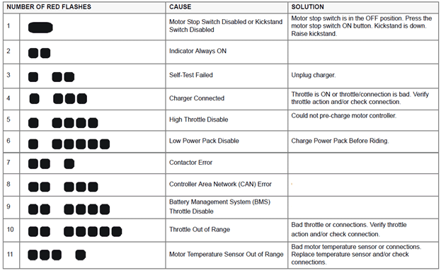

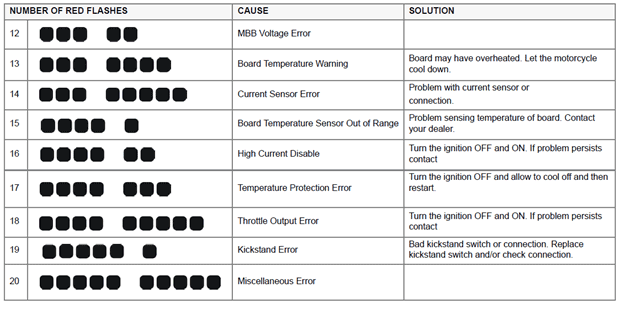
Version 1
| Torque settings for: Brushless Motor Controller Heat Sink Replacement | |
| Item | Torque Setting |
| Brushless Motor Controller Heat Sink Bolts | 11 N•m (8 lb ft) |
 Show Torque Table
Required Tools
• 10mm wrench or socket
• Socket wrench
• 13mm wrench
• 4mm hex wrench
• 5mm hex wrench
Fastener Torques
• Brushless motor controller heat sink bolts 11 N•m (8 lb ft)
Removal Procedure
1. Remove the brushless motor controller. Refer to Brushless Motor Controller Replacement.
2. Remove the heat sink bolts (1), and separate the heat sink from the brushless motor controller.

Installation Procedure
Important: A layer of thermal grease (such as Dow Corning® 340) MUST be applied as described below, before bolting the brushless motor controller to the heat sink.
1. Clean the mounting surface of the brushless motor controller of any old thermo grease.
2. Apply the thermal grease to both the brushless motor controller and the heat sink using a small soft paint roller to ensure an even spread of thermal compound. The most appropriate thickness will look white but with a grayish color still showing through from the controller base or heat sink. Note that too little thermal compound will not fill all gaps of the contact surfaces, but too much thermal compound may prevent the gap from closing up when tightening.
3. Place the heat sink onto the brushless motor controller and rub both surfaces together. This will help transfer the thermal compound between the two surfaces.
Notice: Refer to Fastener Notice in General Information.
4. Install the heat sink bolts (1).
Tighten
Brushless motor controller heat sink bolts to 11 N•m (8 lb ft)
5. Install the brushless motor controller. Refer to Brushless Motor Controller Replacement.

Version 1
| Torque settings for: Brushless Motor Controller Replacement | |
| Item | Torque Setting |
| Skid Plate Bolts | 11 N•m (8 lb ft) |
| Brushless Motor Controller Bolts | 11 N•m (8 lb ft) |
| Brushless Motor Controller Cable Bolts | 11 N•m (8 lb ft) |
 Show Torque Table
Caution: Always perform the High Voltage Disabling procedure prior to servicing any High Voltage component or connection. Proper procedures must be followed!
Required Tools
• Socket wrench
• 13mm socket
• 10mm wrench or socket
• PN 85-05665 Controller Discharge Tool
Fastener Torques
• Skid plate bolts 11 N•m (8 lb ft)
• Brushless motor controller bolts 11 N•m (8 lb ft)
• Brushless motor controller cable bolts 11 N•m (8 lb ft)
Removal Procedure
Caution: Refer to High Voltage Caution in General Information.
Note: Mark the location of all wires and cables prior to removal.
1. Discharge the high voltage system. Refer to High Voltage Disabling.
2. Remove the rubber side panels (XMX CONTROLLER COVER L, XMX CONTROLLER COVER R).
3. Remove the skid plate.
4. Remove the 6 bolts (1) securing the brushless motor control onto the frame and remove the controller.

5. Disconnect the brushless motor controller connector C90.
6. Remove the motor cables (1) C113, C114, C115 from the brushless motor controller.
7. Remove the power pack cables (2) C74, C76, C97, C296 from the brushless motor controller.
8. Remove the heat sink from the controller if required. Refer to Brushless Motor Controller Heat Sink Replacement.

Installation Procedure
1. Install the heat sink onto the controller if required. Refer to Brushless Motor Controller Heat Sink Replacement.
2. Place the controller into position and loosely install the 3 lower bolts.
Notice: Refer to Fastener Notice in General Information.
3. Install the motor cables (1) C113, C114, C115 onto the brushless motor controller.
4. Install the power pack cables (2) C74, C76, C97, C296 onto the brushless motor controller.
Tighten
All cable bolts to 11 N•m (8 lb ft)

5. Install the upper brushless motor controller bolts.
6. Tighten the brushless motor controller bolts (1).
Tighten
Brushless motor controller bolts to 11 N•m (8 lb ft)
7. Install the skid plate.
Tighten
Skid plate bolts to 11 N•m (8 lb ft)
8. Install the rubber side panels.

Version 1
| Torque settings for: Charger Controller Unit Replacement | |
| Item | Torque Setting |
| Seat Bolts | 15 N•m (11 lb ft) |
| Power Pack Charger Bracket Bolts | 6 N•m (54 lb in) |
| Power Pack Charger Nuts | 4 N•m (36 lb in) |
| CCU Bolts | 1.3 N•m (12 lb in) |
 Show Torque Table
Caution: Always perform the High Voltage Disabling procedure prior to servicing any High Voltage component or connection. Proper procedures must be followed!
Required Tools
• 2.5mm hex wrench
• 3mm hex wrench
• 7mm wrench or socket
• 13mm socket
• Socket wrench
• PN 85-05665 Controller Discharge Tool
Fastener Torques
• Seat bolts 15 N•m (11 lb ft)
• Power pack charger bracket bolts 6 N•m (54 lb in)
• Power pack charger nuts 4 N•m (36 lb in)
• Front fairing screws 1.3 N•m (12 lb in)
• CCU bolts 1.3 N•m (12 lb in)
Removal Procedure
Caution: Refer to High Voltage Caution in General Information.
Note: Mark the location of all wires and cables prior to removal.
1. Discharge the high voltage system. Refer to High Voltage Disabling.
2. Remove the seat.
3. Remove the front fender.
4. Remove the fairing assembly (FAIRING FRONT RIGHT POLYPROPOLENE BLACK, FAIRING FRONT LEFT POLYPROPOLENE BLACK, XMX FAIRING CENTER).
5. Remove the power pack chargers (ASSY XMX CHARGER 2S 1P CONFIG MW, ASSY CHARGER CONTROL UNIT). Refer to Power Pack Charger Replacement.
6. Disconnect the Charger Control Unit (CCU) harness connector C57, C205, C206.
7. Remove the top and bottom nut, washer and bolt (1) securing the CCU to the frame. Remove the CCU.

Installation Procedure
1.Program the CCU with the most current firmware.
Notice: Refer to Fastener Notice in General Information.
2. Install the top and bottom bolt, washer and nut securing the CCU to the frame.
Tighten
CCU bolts to 1.3 N•m (12 lb in)
3. Connect the CCU harness connector C57, C205, C206.
4. Install the power pack chargers. Refer to Power Pack Charger Replacement.
5. Install the fairing assembly.
6. Install the front fender.
7. Install the seat.

Version 1
| Torque settings for: DC/DC Converter Replacement | |
| Item | Torque Setting |
| Brushless Motor Controller Top Bracket Bolts | 11 N•m (8 lb ft) |
| DC/DC Converter Bolts | 9 N•m (7 lb ft) |
 Show Torque Table
Caution: Always perform the High Voltage Disabling procedure prior to servicing any High Voltage component or connection. Proper procedures must be followed!
Required Tools
• 4mm hex wrench
• 10mm wrench or socket
• Socket wrench
• PN 85-05665 Controller Discharge Tool
Fastener Torques
• DC/DC Converter nuts 9 N•m (7 lb ft)
• Brushless motor controller top bracket bolts 11 N•m (8 lb ft)
Removal Procedure
Caution: Refer to High Voltage Caution in General Information.
Note: Mark the location of all wires and cables prior to removal.
1. Discharge the high voltage system. Refer to High Voltage Disabling.
2. Remove the rubber side panels (XMX CONTROLLER COVER L, XMX CONTROLLER COVER R).
3. Remove the front fender.
4. Remove the center fairing panel.
5. Remove the brushless motor controller top bracket nuts (1) and bolts (2).

6. Remove the quick charge connector bracket.
7. Disconnect the convertor connector C8.
8. Remove the 2 front and the 2 rear nuts and washers (1) securing the convertor and remove. Note: Top bracket lifted up to show location of fasteners.

Installation Procedure
Notice: Refer to Fastener Notice in General Information.
1. Install the converter onto the mounting studs and install the washers and nuts (1).
Tighten
DC/DC converter nuts to 9 N•m (7 lb in)

2. Connect the converter connector C8.
3. Install the quick charge connector bracket.
4. Install the brushless motor controller top bracket nuts (1) and bolts (2).
5. Install the center fairing panel.
6. Install the front fender.
7. Install the rubber side panels.

Version 1
| Torque settings for: Ignition Switch Replacement | |
| Item | Torque Setting |
| Headlight Adjuster Bolts | 26 N•m (19 lb ft) |
| Fender Bolts | 2 N•m (22 lb in) |
 Show Torque Table
Required Tools
• Philips screwdriver
• Socket wrench
• 3mm hex wrench
• 5mm hex wrench
• 7mm wrench or socket
Fastener Torques
• Headlight adjuster bolts* 26 N•m (19 lb ft)
• Front fender bolts 2 N•m (22 lb in)
*Use LOCTITE® 242® (or equivalent)
Removal Procedure
Note: Mark the location of all wires and cables prior to removal.
1. Remove the fly screen.
2. Remove the headlight bolts (1) from the right and left side, and move the headlight off to the side.

3. Remove the front fender.
4. Remove the two screws (1) securing the ignition switch to the key switch.

5. Remove the right side fairing panel.
6. Disconnect the C274 ignition switch connector.
7. Remove and discard any zip ties necessary.
Installation Procedure
1. Align the post on the key switch with the hole in the ignition switch.
2. Install the ignition switch screws (1).

3. Connect the C274 ignition switch connector.
4. Turn the handlebar all the way to the left. Install zip ties in the same location as removed.
5. Install the headlight and the right and left bolts (1).
6. Install the front fender.
7. Install the fly screen. Ensure that ground C239 is between the fly screen bolt and the bracket.
8. Adjust the headlight. Refer to Headlight Adjustment.

Version 1
| Torque settings for: Key Switch Replacement | |
| Item | Torque Setting |
| Headlight Adjuster Bolts | 26 N•m (19 lb ft) |
| Front Fender Bolts | 2 N•m (22 lb in) |
 Show Torque Table
Required Tools
• Philips screwdriver
• Socket wrench
• 3mm hex wrench
• 5mm hex wrench
• 7mm wrench or socket
Fastener Torques
• Headlight adjuster bolts* 26 N•m (19 lb ft)
• Front fender bolts 2 N•m (22 lb in)
*Use LOCTITE® 242® (or equivalent)
Removal Procedure
1. Remove the fly screen.
2. Remove the headlight bolts (1) from the right and left side, and move the headlight off to the side.

3. Remove the front fender.
4. Remove the two screws (1) securing the ignition switch to the key switch. Move switch off to the side.

5. Remove the breakaway bolts (1) and remove the lock cylinder. To remove the bolt you must use a bolt extractor. Follow the manufacturer's instructions for correct use of the bolt extractor.

Installation Procedure
1. Install LOCTITE® 271™ to the threads of the key switch bolts.
2. Install the lock cylinder and bolts. Tighten the bolts until the nut head breaks off (1).

3. Align the post on the key switch with the hole in the ignition switch.
4. Install the ignition switch screws (1).

5. Install the headlight and the right and left bolts (1).
6. Install the front fender.
7. Install the fly screen. Ensure that ground C239 is between the fly screen bolt and the bracket.
8. Adjust the headlight. Refer to Headlight Adjustment.

Version 1
| Torque settings for: Main Bike Board Replacement | |
| Item | Torque Setting |
| Brushless Motor Controller Top Bracket Bolts | 11 N•m (8 lb ft) |
| Main Bike Board Bolts | 1.3 N•m (12 lb in) |
 Show Torque Table
Caution: Always perform the High Voltage Disabling procedure prior to servicing any High Voltage component or connection. Proper procedures must be followed!
Required Tools
• 2.5mm hex wrench
• 3mm hex wrench
• 4mm hex wrench
• 7mm wrench or socket
• 10mm wrench or socket
• Socket wrench
• PN 85-05665 Controller Discharge Tool
Fastener Torques
• Main bike board bolts 1.3 N•m (12 lb in)
• Brushless motor controller top bracket bolts 11 N•m (8 lb ft)
Removal Procedure
Caution: Refer to High Voltage Caution in General Information.
Note: Mark the location of all wires and cables prior to removal.
1. Discharge the high voltage system. Refer to High Voltage Disabling.
2. Remove the rubber side panels (XMX CONTROLLER COVER L, XMX CONTROLLER COVER R).
3. Remove the front fender.
4. Remove the center fairing panel.
5. Remove the brushless motor controller top bracket nuts (1) and bolts (2).

6. Remove the bolts (1) and remove the cover (2). Note: The front bolt has a nut on the bottom that has to be held.

7. Disconnect the main bike board (MBB) connectors C1 and C2, and remove the MBB.
Installation Procedure
1. Install the MBB and connect the C1 and C2 connectors.
Notice: Refer to Fastener Notice in General Information.
2. Install the cover (2) and bolts (1).
Tighten
MBB bolts to 1.3 N•m (12 lb in)

3. Install the brushless motor controller top bracket nuts (1) and bolts (2).
4. Install the center fairing panel.
5. Install the front fender.
6. Install the rubber side panels.

Version 1
Required Tools
• Philips screwdriver
• 8mm wrench or socket
• Socket wrench
• 3mm hex wrench
Removal Procedure
1. Remove the instrument panel lower cover.
2. Disconnect the right handlebar control harness connector C275. Note the location of the zip ties for reassembly.
3. Remove and discard the zip ties.
4. Remove the 2 master cylinder bolts holding the master cylinder onto the handlebar. Note: Do not remove the hydraulic brake hose.
5. Remove the 2 philips (1) from the right handlebar switch, and remove the switch.

Installation Procedure
1. Place the right handlebar control onto the handlebar aligning the switch pin with the hole in the handlebar.
2. Securely tighten the two screws (1). Do not over tighten.
3. Connect the right handlebar control harness connector C275.
4. Install new zip ties in the same location as removed.
5. Install the instrument panel lower cover.

Version 1
| Torque settings for: Throttle Replacement | |
| Item | Torque Setting |
| Front Fender Bolts | 2 N•m (22 lb in) |
| Center Fairing Screws | 1.3 N•m (12 lb in) |
 Show Torque Table
Required Tools
• Philips screwdriver
• 7mm socket or wrench
• Socket wrench
• 3mm hex wrench
Fastener Torques
• Center fairing screws 1.3 N•m (12 lb in)
• Front fender bolts 2 N•m (22 lb in)
Removal Procedure
1. Remove the front fender.
2. Remove the center fairing panel.
3. Disconnect the throttle harness connector C5. Note the location of the zip ties for reassembly.
4. Remove and discard the zip ties.
5. Loosen the two throttle screws (1) and slide the throttle off of the handlebar.

Installation Procedure
1. Slide the throttle onto the handlebar.
2. Securely tighten the two screws (1). Do not over tighten.
3. Twist the throttle and verify that the throttle is smooth and returns correctly.
4. Connect the throttle harness connector C5.
5. Install new zip ties in the same location as removed.
6. Install the center fairing panel.
7. Install the front fender.

Version 1
| Torque settings for: Motor Replacement | |
| Item | Torque Setting |
| Right Motor Bolts | 27 N•m (20 lb ft) |
| Left Rear Top And Bottom Motor Bolts | 25 N•m (26 lb ft) |
| Left Front Top And Bottom Motor Bolts | 27 N•m (20 lb ft) |
| Brushless Motor Controller Cable Bolts | 11 N•m (8 lb ft) |
| Swingarm Pivot Bolts | 102 N•m (75 lb ft) |
| Lower Shock Nut And Bolt | 52 N•m (38 lb ft) |
 Show Torque Table
Caution: Always perform the High Voltage Disabling procedure prior to servicing any High Voltage component or connection. Proper procedures must be followed!
Required Tools
• 5mm hex wrench
• 6mm hex wrench
• 10mm hex wrench
• 21mm wrench
• 13mm wrench
• PN 85-05665 Controller Discharge Tool
Fastener Torques
• Right motor bolts* 27 N•m (20 lb ft)
• Left rear top and bottom motor bolts* 35 N•m (26 lb ft)
• Left front top and bottom motor bolts* 27 N•m (20 lb ft)
• Swingarm pivot bolts** 102 N•m (75 lb ft)
• Brushless motor controller cable bolts 11 N•m (8 lb ft)
• Lower shock nut and bolt 52 N•m (38 lb ft)
*Use Polylube 1000TM (or equivalent)
**Use LOCTITE® 242® (or equivalent)
Removal Procedure
Caution: Refer to High Voltage Caution in General Information.
Note: Mark the location of all wires and cables prior to removal.
1. Discharge the high voltage system. Refer to High Voltage Disabling.
2. Remove the controller cable bolts (1).

3. Disconnect C14 motor harness connector.
4. Remove the swingarm. Refer to Swingarm Replacement.
5. Loosen the 4 left side motor bolts (1), loosen the right side motor bolts.

6. Loosen the right side motor spacer nut (1), do this for all 4 spacers. (MOTOR JACK SCREW OUTER, MOTOR JACK SCREW INNER)
7. Remove the motor bolts and lower the motor out the bottom of the motorcycle.

Installation Procedure
1. Place the motor into the frame from the bottom, routing the cable to the brushless motor controller.
Notice: Refer to Fastener Notice in General Information.
2. Install the 4 left side motor bolts (1) and tighten.
Tighten
Left rear top and bottom motor bolts to 35 N•m (26 lb ft)
Left front top and bottom motor bolts to 27 N•m (20 lb ft)

3. Install the 4 motor spacers and gently expand the nut (1) to take up the clearance between the motor and frame.

4. Install the 4 right side motor bolts and tighten.
Tighten
Motor bolts to 27 N•m (20 lb ft)
5. Install the drive belt onto the motor pulley.
6. Install the swingarm. Refer to Swingarm Replacement.
7. Install the motor cables (1) onto the brushless motor controller.
Tighten
Brushless motor controller bolts to 11 N•m (8 lb ft)
8. Connect C14 motor harness connector.
9. Adjust the belt tension. Refer to Belt Tension Adjustment.

Version 1
| Torque settings for: Power Pack Charger Replacement | |
| Item | Torque Setting |
| Seat Bolts | 15 N•m (11 lb ft) |
| Bracket To Frame Bolts | 6 N•m (54 lb in) |
| Bracket To Power Pack Charger Nuts | 4 N•m (36 lb in) |
| AC Charger Connector Nuts | 1.3 N•m (12 lb in) |
| Front Fairing Screws | 1.3 N•m (12 lb in) |
 Show Torque Table
Caution: Always perform the High Voltage Disabling procedure prior to servicing any High Voltage component or connection. Proper procedures must be followed!
Required Tools
• Socket wrench
• 13mm socket
• 3mm hex wrench
• 7mm wrench or socket
• PN 85-05665 Controller Discharge Tool
Fastener Torques
• Bracket to frame bolts 6 N•m (54 lb in)
• Bracket to power pack charger nuts 4 N•m (36 lb in)
• AC charger connector nuts 1.3 N•m (12 lb in)
• Seat bolts 15 N•m (11 lb ft)
• Front fairing screws 1.3 N•m (12 lb in)
Removal Procedure
Caution: Refer to High Voltage Caution in General Information.
Note: Mark the location of all wires and cables prior to removal.
1. Discharge the high voltage system. Refer to High Voltage Disabling.
2. Remove the front fender.
3. Remove the seat.
4. Remove the fairing assembly (FAIRING FRONT RIGHT POLYPROPOLENE BLACK, FAIRING FRONT LEFT POLYPROPOLENE BLACK, XMX FAIRING CENTER).
5. Remove the 2 nuts and washers (1) from the AC plug connector and remove the connector from the studs.
6. Loosen the 4 right side nuts (2).

7. Disconnect the horn connectors C32.
8. Remove the 4 left side bracket bolts (1).
9. Noting there locations disconnect the 2 connectors from the charger control unit (CCU).
10. Slide the power pack chargers out from the frame.
11. Remove the 2 mounting brackets and AC connector cover from the chargers (CHARGER - MEANWELL HLG-320H-54AETI, ASSY XMX CHARGER 2S 1P CONFIG MW).

Installation Procedure
Notice: Refer to Fastener Notice in General Information.
1. Install the 2 mounting brackets onto the chargers.
Tighten
Bracket to charger nuts 4 N•m (36 lb in)
2. Slide the chargers into the frame and connect the connectors onto the CCU.
3. Slide the chargers onto the studs on the right side, ensure that the washers are between the chargers and the nuts.
4. Apply loctite® 242 to the threaded portion of the charger bracket bolts.
5. Install the 4 bolts (1) securing the charger brackets to the frame.
Tighten
Bracket to frame bolts 6 N•m (54 lb in)
6. Connect the horn connectors C32.

7. Tighten the charger nuts (2) on the right side.
Tighten
Bracket to charger nuts 4 N•m (36 lb in)
8. Install the AC connector cover onto the charger AC power cord.
9. Apply loctite® 242 to the threaded portion of the AC connector mounting studs.
10. Install the AC connector onto the studs and install the washers and nuts.
Tighten
AC charger connector nuts 1.3 N•m (12 lb in)
11. Install the fairing assembly.
12. Install the front fender.
13. Install the seat.

Version 1
Power Pack
The battery is located within the power pack and requires no special break in period. The charging time will remain the same if the onboard charger is connected to a 120 V AC or a 240 V AC supply.
The normal recharging time of the power pack to 100% is usually less than 3 hours in mild ambient temperatures. Out of the normal temperature range charging and run-time times will vary. The power pack should not be used outside of the range of 23°F to 140°F (-5°C to 60°C); the Battery Management System (BMS) turns off the power controller outside of this range.
Note: The Battery will not charge if below 0°C or 32°F.
WARNING! Only charge the Zero power pack with the Zero charger.
Power Pack Charger
Keep the power pack connected to the charger when the motorcycle is sitting in storage or if it will be sitting unused for more than 30 days. The power pack must be charged within 24 hours if fully discharged, and charged within 90 days if stored fully charged. Zero recommends to plug in the Zero Motorcycle after 30 days, even if fully charged. Leave the Zero Motorcycle plugged in whenever possible.
WARNING! Only charge the Zero power pack with the Zero charger. The chargers are located under the fairing panels in front of the front power pack.
When charging the motorcycle’s power pack, the charger can be left ON, even after the power pack is fully charged. There are two possible cases that can occur:
• When connected to the charger, the power pack will receive a full charge. Once fully charged, the charger will check the status of the power pack once every 72 hours to ensure that it maintains a full charge. When fully charged, a green light illuminates on the charger. Should the charger not read that the power pack is full, it continues to attempt to fully charge the power pack. In this event the green light may not illuminate; however, the power pack may be fully charged. To ensure that the power pack is charged, check the charge indicator on the dash display prior to riding.
• If the power pack terminates the charge before the charger reaches the state previously mentioned, then the charger continues to cycle and tops off the power pack until the power pack is removed from the charger, or the charger reaches the complete state previously noted.
Charging the Power Pack
WARNING! Charge the Zero power pack with the Zero charger.
It is possible for lithium ion cells to overheat and fail.
Note: Charge the Zero Power pack in a location that is well-ventilated and away from combustible materials. If charging the motorcycle outdoors, avoid charging in the rain.
The maximum power pack internal charging temperature is 131°F (55°C). If the power pack’s internal temperature is over 131°F (55°C), it will not accept a charge until it is moved to a cooler location. Also, if the power pack has just been run hard, it may internally be above 131°F (55°C) even if the ambient temperature is lower. If you experience a power pack that will not take a charge, you should ensure the internal temperature is below 131°F (55°C). If the power pack was recently run and it will not take a charge, the power pack should cool and begin taking a charge in around 30 minutes or less. The maximum charging temperature cutoff is a power pack longevity feature. Charging at higher temperatures can shorten the life of the power pack.
Note: Frequent top off charging is good for the power pack’s life span, so do not hesitate to charge frequently.
Quick Charging (Off Board Accessory Charger)
The “scalable” quick charging feature allows up to three supplemental accessory chargers (in addition to the existing integrated charger) to be connected to the motorcycle. Use of supplemental accessory chargers can reduce the charging time by up to 70%.
Note: The time for charging the motorcycle using quick charging will vary with the number of chargers used.
The accessory charging connector (1) is located above the motor. For more information on how to connect additional chargers, refer to the quick charger’s owner’s manual.

Cold and Hot Weather Considerations
Cold Weather
Cold Weather operation of the motorcycle has no permanent impact on its battery pack/cells; however, the rider may see a reduction in range due to the effect cold temperature has on the amount of energy the pack/cells can release. The colder the weather, the greater the effect; so that, as compared to operation in 80°F (27°C) ambient, at 30°F (-1°C) ambient the rider could experience a temporary reduction in range of up to 30%. In extreme cold weather the motorcycle may also experience a temporary reduction in power and, correspondingly, achieved top speed. It is not recommended that the motorcycle be ridden while its battery temperature is below 23°F (-5°C). If it is, its battery needs to be put on the charger at a temperature above 32°F (0°C) as soon as the ride is concluded. It is worth noting that the Battery Management System (BMS) will not allow the battery to be discharged below -22°F (-30°C), which is the absolute lowest discharge temperature prescribed by the cell manufacturer.
Storage of the motorcycle for the winter in a non-heated garage is acceptable, as long as:
1. the coldest temperature in the garage does not fall below -31°F (-35°C)
2. the battery is left on the charger continuously
3. the battery is initially topped off at a temperature above 32°F (0°C)
Storage temperatures below -31°F (-35°C) may result in accelerated permanent decay of the battery performance, and hence, it is not recommended. Above this temperature, working as a system with the BMS, the charger will ensure the battery survives winter storage with no permanent damage, even if the temperatures dip well below freezing for weeks at a time. Note that, to prevent battery damage, the BMS will prevent the charger from charging the battery at a temperature below 32°F (0°C). Again, as long as the battery was initially topped off by the charger above 32°F (0°C) and remains on the charger through the winter at temperatures above -31°F (-35°C), the system will guard the battery from damage.
Hot Weather Operation
Operation of the motorcycle in hot temperatures should not result in any noticeable performance changes. However, the BMS will not allow motorcycle operation and its associated battery discharge above 140°F (60°C), as measured at the battery. In hot temperatures greater than 110°F (43°C), the charger reduces its charge current to the battery, increasing charge time accordingly; the hotter the ambient temperature, the greater the effect. Above a battery temperature of 131°F (55°C), the BMS will no longer allow charging.
Note: Storing the motorcycle or its battery in direct sunlight in ambient temperatures above 105°F (41°C) may result in accelerated permanent decay of battery performance, and hence, it is not recommended.
Battery Management System (BMS)
Every power pack contains a Battery Management System (BMS) which monitors the condition of the cells, and optimizes the charging process to provide the highest-performance, longest-range, and longest life for the power pack. The BMS safeguards the power pack by means of safety interlocks. These interlocks turn off or control certain operations that could damage the power pack. The BMS also monitors the power pack for a host of predefined conditions, and then takes actions according to those conditions. The BMS is sealed inside the power pack.
Safety Interlocks
If the BMS detects a serious internal fault, it can take either or both of two actions to prevent damage to the power pack:
• Throttle Disable. The BMS disables the throttle if the power pack is empty, or if the BMS detects certain serious internal problems. The motorcycle can’t be ridden until the problem is resolved.
• Charger Disable. The BMS prevents charging if it detects certain serious internal problems - even if the power pack is connected to a charger and plugged in to AC power. The power pack cannot be charged until the problem is resolved.
Throttle Disable Interlock
The BMS communicates with the main motorcycle control module. The BMS can send a signal to the main motorcycle controller requesting that the throttle control on the motorcycle be disabled. When the throttle control is disabled, the motor will not deliver power to the rear wheel, and the motorcycle cannot be ridden. If the throttle is disabled while riding, the motorcycle will cease to provide power, and the operator must pull over to a safe location. All conditions which would cause the BMS to disable the throttle are also signaled by a flash code pattern at self-test. If you suspect that the BMS has disabled the throttle control on your motorcycle, turn the key switch OFF and back ON again to enter self-test mode. The flash code pattern from the BMS reports any of the error conditions which would cause the BMS to disable the throttle.
• Power Pack Empty
• Too Hot
• Power Pack Unbalanced
Charger-Disable Interlock
When the charger is attached and plugged in to AC power, the BMS communicates with the charger. The BMS can send a signal to the charger requesting that charging terminates immediately. When the charger is disabled, the indicator lights on the charger displays that charging has stopped. There are two conditions that cause the BMS to disable charging:
1.Too hot
The BMS detects an internal power pack temperature above 131°F (55°C).
2.Too cold
The BMS detects an internal power pack temperature below 32°F (0°C).
Version 1
| Torque settings for: Key Switch Replacement | |
| Item | Torque Setting |
| Headlight Adjuster Bolts | 26 N•m (19 lb ft) |
| Front Fender Bolts | 2 N•m (22 lb in) |
 Show Torque Table
Required Tools
• Philips screwdriver
• Socket wrench
• 3mm hex wrench
• 5mm hex wrench
• 7mm wrench or socket
Fastener Torques
• Headlight adjuster bolts* 26 N•m (19 lb ft)
• Front fender bolts 2 N•m (22 lb in)
*Use LOCTITE® 242® (or equivalent)
Removal Procedure
1. Remove the fly screen.
2. Remove the headlight bolts (1) from the right and left side, and move the headlight off to the side.

3. Remove the front fender.
4. Remove the two screws (1) securing the ignition switch to the key switch. Move switch off to the side.

5. Remove the breakaway bolts (1) and remove the lock cylinder. To remove the bolt you must use a bolt extractor. Follow the manufacturer's instructions for correct use of the bolt extractor.

Installation Procedure
1. Install LOCTITE® 271™ to the threads of the key switch bolts.
2. Install the lock cylinder and bolts. Tighten the bolts until the nut head breaks off (1).

3. Align the post on the key switch with the hole in the ignition switch.
4. Install the ignition switch screws (1).

5. Install the headlight and the right and left bolts (1).
6. Install the front fender.
7. Install the fly screen. Ensure that ground C239 is between the fly screen bolt and the bracket.
8. Adjust the headlight. Refer to Headlight Adjustment.

Version 1
| Torque settings for: Main Bike Board Replacement | |
| Item | Torque Setting |
| Brushless Motor Controller Top Bracket Bolts | 11 N•m (8 lb ft) |
| Main Bike Board Bolts | 1.3 N•m (12 lb in) |
 Show Torque Table
Caution: Always perform the High Voltage Disabling procedure prior to servicing any High Voltage component or connection. Proper procedures must be followed!
Required Tools
• 2.5mm hex wrench
• 3mm hex wrench
• 4mm hex wrench
• 7mm wrench or socket
• 10mm wrench or socket
• Socket wrench
• PN 85-05665 Controller Discharge Tool
Fastener Torques
• Main bike board bolts 1.3 N•m (12 lb in)
• Brushless motor controller top bracket bolts 11 N•m (8 lb ft)
Removal Procedure
Caution: Refer to High Voltage Caution in General Information.
Note: Mark the location of all wires and cables prior to removal.
1. Discharge the high voltage system. Refer to High Voltage Disabling.
2. Remove the rubber side panels (XMX CONTROLLER COVER L, XMX CONTROLLER COVER R).
3. Remove the front fender.
4. Remove the center fairing panel.
5. Remove the brushless motor controller top bracket nuts (1) and bolts (2).

6. Remove the bolts (1) and remove the cover (2). Note: The front bolt has a nut on the bottom that has to be held.

7. Disconnect the main bike board (MBB) connectors C1 and C2, and remove the MBB.
Installation Procedure
1. Install the MBB and connect the C1 and C2 connectors.
Notice: Refer to Fastener Notice in General Information.
2. Install the cover (2) and bolts (1).
Tighten
MBB bolts to 1.3 N•m (12 lb in)

3. Install the brushless motor controller top bracket nuts (1) and bolts (2).
4. Install the center fairing panel.
5. Install the front fender.
6. Install the rubber side panels.

Version 1
Required Tools
• Philips screwdriver
• 8mm wrench or socket
• Socket wrench
• 3mm hex wrench
Removal Procedure
1. Remove the instrument panel lower cover.
2. Disconnect the right handlebar control harness connector C275. Note the location of the zip ties for reassembly.
3. Remove and discard the zip ties.
4. Remove the 2 master cylinder bolts holding the master cylinder onto the handlebar. Note: Do not remove the hydraulic brake hose.
5. Remove the 2 philips (1) from the right handlebar switch, and remove the switch.

Installation Procedure
1. Place the right handlebar control onto the handlebar aligning the switch pin with the hole in the handlebar.
2. Securely tighten the two screws (1). Do not over tighten.
3. Connect the right handlebar control harness connector C275.
4. Install new zip ties in the same location as removed.
5. Install the instrument panel lower cover.

Version 1
| Torque settings for: Throttle Replacement | |
| Item | Torque Setting |
| Front Fender Bolts | 2 N•m (22 lb in) |
| Center Fairing Screws | 1.3 N•m (12 lb in) |
 Show Torque Table
Required Tools
• Philips screwdriver
• 7mm socket or wrench
• Socket wrench
• 3mm hex wrench
Fastener Torques
• Center fairing screws 1.3 N•m (12 lb in)
• Front fender bolts 2 N•m (22 lb in)
Removal Procedure
1. Remove the front fender.
2. Remove the center fairing panel.
3. Disconnect the throttle harness connector C5. Note the location of the zip ties for reassembly.
4. Remove and discard the zip ties.
5. Loosen the two throttle screws (1) and slide the throttle off of the handlebar.

Installation Procedure
1. Slide the throttle onto the handlebar.
2. Securely tighten the two screws (1). Do not over tighten.
3. Twist the throttle and verify that the throttle is smooth and returns correctly.
4. Connect the throttle harness connector C5.
5. Install new zip ties in the same location as removed.
6. Install the center fairing panel.
7. Install the front fender.

Version 1
| Torque settings for: Motor Replacement | |
| Item | Torque Setting |
| Right Motor Bolts | 27 N•m (20 lb ft) |
| Left Rear Top And Bottom Motor Bolts | 25 N•m (26 lb ft) |
| Left Front Top And Bottom Motor Bolts | 27 N•m (20 lb ft) |
| Brushless Motor Controller Cable Bolts | 11 N•m (8 lb ft) |
| Swingarm Pivot Bolts | 102 N•m (75 lb ft) |
| Lower Shock Nut And Bolt | 52 N•m (38 lb ft) |
 Show Torque Table
Caution: Always perform the High Voltage Disabling procedure prior to servicing any High Voltage component or connection. Proper procedures must be followed!
Required Tools
• 5mm hex wrench
• 6mm hex wrench
• 10mm hex wrench
• 21mm wrench
• 13mm wrench
• PN 85-05665 Controller Discharge Tool
Fastener Torques
• Right motor bolts* 27 N•m (20 lb ft)
• Left rear top and bottom motor bolts* 35 N•m (26 lb ft)
• Left front top and bottom motor bolts* 27 N•m (20 lb ft)
• Swingarm pivot bolts** 102 N•m (75 lb ft)
• Brushless motor controller cable bolts 11 N•m (8 lb ft)
• Lower shock nut and bolt 52 N•m (38 lb ft)
*Use Polylube 1000TM (or equivalent)
**Use LOCTITE® 242® (or equivalent)
Removal Procedure
Caution: Refer to High Voltage Caution in General Information.
Note: Mark the location of all wires and cables prior to removal.
1. Discharge the high voltage system. Refer to High Voltage Disabling.
2. Remove the controller cable bolts (1).

3. Disconnect C14 motor harness connector.
4. Remove the swingarm. Refer to Swingarm Replacement.
5. Loosen the 4 left side motor bolts (1), loosen the right side motor bolts.

6. Loosen the right side motor spacer nut (1), do this for all 4 spacers. (MOTOR JACK SCREW OUTER, MOTOR JACK SCREW INNER)
7. Remove the motor bolts and lower the motor out the bottom of the motorcycle.

Installation Procedure
1. Place the motor into the frame from the bottom, routing the cable to the brushless motor controller.
Notice: Refer to Fastener Notice in General Information.
2. Install the 4 left side motor bolts (1) and tighten.
Tighten
Left rear top and bottom motor bolts to 35 N•m (26 lb ft)
Left front top and bottom motor bolts to 27 N•m (20 lb ft)

3. Install the 4 motor spacers and gently expand the nut (1) to take up the clearance between the motor and frame.

4. Install the 4 right side motor bolts and tighten.
Tighten
Motor bolts to 27 N•m (20 lb ft)
5. Install the drive belt onto the motor pulley.
6. Install the swingarm. Refer to Swingarm Replacement.
7. Install the motor cables (1) onto the brushless motor controller.
Tighten
Brushless motor controller bolts to 11 N•m (8 lb ft)
8. Connect C14 motor harness connector.
9. Adjust the belt tension. Refer to Belt Tension Adjustment.

Version 1
| Torque settings for: Power Pack Charger Replacement | |
| Item | Torque Setting |
| Seat Bolts | 15 N•m (11 lb ft) |
| Bracket To Frame Bolts | 6 N•m (54 lb in) |
| Bracket To Power Pack Charger Nuts | 4 N•m (36 lb in) |
| AC Charger Connector Nuts | 1.3 N•m (12 lb in) |
| Front Fairing Screws | 1.3 N•m (12 lb in) |
 Show Torque Table
Caution: Always perform the High Voltage Disabling procedure prior to servicing any High Voltage component or connection. Proper procedures must be followed!
Required Tools
• Socket wrench
• 13mm socket
• 3mm hex wrench
• 7mm wrench or socket
• PN 85-05665 Controller Discharge Tool
Fastener Torques
• Bracket to frame bolts 6 N•m (54 lb in)
• Bracket to power pack charger nuts 4 N•m (36 lb in)
• AC charger connector nuts 1.3 N•m (12 lb in)
• Seat bolts 15 N•m (11 lb ft)
• Front fairing screws 1.3 N•m (12 lb in)
Removal Procedure
Caution: Refer to High Voltage Caution in General Information.
Note: Mark the location of all wires and cables prior to removal.
1. Discharge the high voltage system. Refer to High Voltage Disabling.
2. Remove the front fender.
3. Remove the seat.
4. Remove the fairing assembly (FAIRING FRONT RIGHT POLYPROPOLENE BLACK, FAIRING FRONT LEFT POLYPROPOLENE BLACK, XMX FAIRING CENTER).
5. Remove the 2 nuts and washers (1) from the AC plug connector and remove the connector from the studs.
6. Loosen the 4 right side nuts (2).

7. Disconnect the horn connectors C32.
8. Remove the 4 left side bracket bolts (1).
9. Noting there locations disconnect the 2 connectors from the charger control unit (CCU).
10. Slide the power pack chargers out from the frame.
11. Remove the 2 mounting brackets and AC connector cover from the chargers (CHARGER - MEANWELL HLG-320H-54AETI, ASSY XMX CHARGER 2S 1P CONFIG MW).

Installation Procedure
Notice: Refer to Fastener Notice in General Information.
1. Install the 2 mounting brackets onto the chargers.
Tighten
Bracket to charger nuts 4 N•m (36 lb in)
2. Slide the chargers into the frame and connect the connectors onto the CCU.
3. Slide the chargers onto the studs on the right side, ensure that the washers are between the chargers and the nuts.
4. Apply loctite® 242 to the threaded portion of the charger bracket bolts.
5. Install the 4 bolts (1) securing the charger brackets to the frame.
Tighten
Bracket to frame bolts 6 N•m (54 lb in)
6. Connect the horn connectors C32.

7. Tighten the charger nuts (2) on the right side.
Tighten
Bracket to charger nuts 4 N•m (36 lb in)
8. Install the AC connector cover onto the charger AC power cord.
9. Apply loctite® 242 to the threaded portion of the AC connector mounting studs.
10. Install the AC connector onto the studs and install the washers and nuts.
Tighten
AC charger connector nuts 1.3 N•m (12 lb in)
11. Install the fairing assembly.
12. Install the front fender.
13. Install the seat.

Version 1
Power Pack
The battery is located within the power pack and requires no special break in period. The charging time will remain the same if the onboard charger is connected to a 120 V AC or a 240 V AC supply.
The normal recharging time of the power pack to 100% is usually less than 3 hours in mild ambient temperatures. Out of the normal temperature range charging and run-time times will vary. The power pack should not be used outside of the range of 23°F to 140°F (-5°C to 60°C); the Battery Management System (BMS) turns off the power controller outside of this range.
Note: The Battery will not charge if below 0°C or 32°F.
WARNING! Only charge the Zero power pack with the Zero charger.
Power Pack Charger
Keep the power pack connected to the charger when the motorcycle is sitting in storage or if it will be sitting unused for more than 30 days. The power pack must be charged within 24 hours if fully discharged, and charged within 90 days if stored fully charged. Zero recommends to plug in the Zero Motorcycle after 30 days, even if fully charged. Leave the Zero Motorcycle plugged in whenever possible.
WARNING! Only charge the Zero power pack with the Zero charger. The chargers are located under the fairing panels in front of the front power pack.
When charging the motorcycle’s power pack, the charger can be left ON, even after the power pack is fully charged. There are two possible cases that can occur:
• When connected to the charger, the power pack will receive a full charge. Once fully charged, the charger will check the status of the power pack once every 72 hours to ensure that it maintains a full charge. When fully charged, a green light illuminates on the charger. Should the charger not read that the power pack is full, it continues to attempt to fully charge the power pack. In this event the green light may not illuminate; however, the power pack may be fully charged. To ensure that the power pack is charged, check the charge indicator on the dash display prior to riding.
• If the power pack terminates the charge before the charger reaches the state previously mentioned, then the charger continues to cycle and tops off the power pack until the power pack is removed from the charger, or the charger reaches the complete state previously noted.
Charging the Power Pack
WARNING! Charge the Zero power pack with the Zero charger.
It is possible for lithium ion cells to overheat and fail.
Note: Charge the Zero Power pack in a location that is well-ventilated and away from combustible materials. If charging the motorcycle outdoors, avoid charging in the rain.
The maximum power pack internal charging temperature is 131°F (55°C). If the power pack’s internal temperature is over 131°F (55°C), it will not accept a charge until it is moved to a cooler location. Also, if the power pack has just been run hard, it may internally be above 131°F (55°C) even if the ambient temperature is lower. If you experience a power pack that will not take a charge, you should ensure the internal temperature is below 131°F (55°C). If the power pack was recently run and it will not take a charge, the power pack should cool and begin taking a charge in around 30 minutes or less. The maximum charging temperature cutoff is a power pack longevity feature. Charging at higher temperatures can shorten the life of the power pack.
Note: Frequent top off charging is good for the power pack’s life span, so do not hesitate to charge frequently.
Quick Charging (Off Board Accessory Charger)
The “scalable” quick charging feature allows up to three supplemental accessory chargers (in addition to the existing integrated charger) to be connected to the motorcycle. Use of supplemental accessory chargers can reduce the charging time by up to 70%.
Note: The time for charging the motorcycle using quick charging will vary with the number of chargers used.
The accessory charging connector (1) is located above the motor. For more information on how to connect additional chargers, refer to the quick charger’s owner’s manual.

Cold and Hot Weather Considerations
Cold Weather
Cold Weather operation of the motorcycle has no permanent impact on its battery pack/cells; however, the rider may see a reduction in range due to the effect cold temperature has on the amount of energy the pack/cells can release. The colder the weather, the greater the effect; so that, as compared to operation in 80°F (27°C) ambient, at 30°F (-1°C) ambient the rider could experience a temporary reduction in range of up to 30%. In extreme cold weather the motorcycle may also experience a temporary reduction in power and, correspondingly, achieved top speed. It is not recommended that the motorcycle be ridden while its battery temperature is below 23°F (-5°C). If it is, its battery needs to be put on the charger at a temperature above 32°F (0°C) as soon as the ride is concluded. It is worth noting that the Battery Management System (BMS) will not allow the battery to be discharged below -22°F (-30°C), which is the absolute lowest discharge temperature prescribed by the cell manufacturer.
Storage of the motorcycle for the winter in a non-heated garage is acceptable, as long as:
1. the coldest temperature in the garage does not fall below -31°F (-35°C)
2. the battery is left on the charger continuously
3. the battery is initially topped off at a temperature above 32°F (0°C)
Storage temperatures below -31°F (-35°C) may result in accelerated permanent decay of the battery performance, and hence, it is not recommended. Above this temperature, working as a system with the BMS, the charger will ensure the battery survives winter storage with no permanent damage, even if the temperatures dip well below freezing for weeks at a time. Note that, to prevent battery damage, the BMS will prevent the charger from charging the battery at a temperature below 32°F (0°C). Again, as long as the battery was initially topped off by the charger above 32°F (0°C) and remains on the charger through the winter at temperatures above -31°F (-35°C), the system will guard the battery from damage.
Hot Weather Operation
Operation of the motorcycle in hot temperatures should not result in any noticeable performance changes. However, the BMS will not allow motorcycle operation and its associated battery discharge above 140°F (60°C), as measured at the battery. In hot temperatures greater than 110°F (43°C), the charger reduces its charge current to the battery, increasing charge time accordingly; the hotter the ambient temperature, the greater the effect. Above a battery temperature of 131°F (55°C), the BMS will no longer allow charging.
Note: Storing the motorcycle or its battery in direct sunlight in ambient temperatures above 105°F (41°C) may result in accelerated permanent decay of battery performance, and hence, it is not recommended.
Battery Management System (BMS)
Every power pack contains a Battery Management System (BMS) which monitors the condition of the cells, and optimizes the charging process to provide the highest-performance, longest-range, and longest life for the power pack. The BMS safeguards the power pack by means of safety interlocks. These interlocks turn off or control certain operations that could damage the power pack. The BMS also monitors the power pack for a host of predefined conditions, and then takes actions according to those conditions. The BMS is sealed inside the power pack.
Safety Interlocks
If the BMS detects a serious internal fault, it can take either or both of two actions to prevent damage to the power pack:
• Throttle Disable. The BMS disables the throttle if the power pack is empty, or if the BMS detects certain serious internal problems. The motorcycle can’t be ridden until the problem is resolved.
• Charger Disable. The BMS prevents charging if it detects certain serious internal problems - even if the power pack is connected to a charger and plugged in to AC power. The power pack cannot be charged until the problem is resolved.
Throttle Disable Interlock
The BMS communicates with the main motorcycle control module. The BMS can send a signal to the main motorcycle controller requesting that the throttle control on the motorcycle be disabled. When the throttle control is disabled, the motor will not deliver power to the rear wheel, and the motorcycle cannot be ridden. If the throttle is disabled while riding, the motorcycle will cease to provide power, and the operator must pull over to a safe location. All conditions which would cause the BMS to disable the throttle are also signaled by a flash code pattern at self-test. If you suspect that the BMS has disabled the throttle control on your motorcycle, turn the key switch OFF and back ON again to enter self-test mode. The flash code pattern from the BMS reports any of the error conditions which would cause the BMS to disable the throttle.
• Power Pack Empty
• Too Hot
• Power Pack Unbalanced
Charger-Disable Interlock
When the charger is attached and plugged in to AC power, the BMS communicates with the charger. The BMS can send a signal to the charger requesting that charging terminates immediately. When the charger is disabled, the indicator lights on the charger displays that charging has stopped. There are two conditions that cause the BMS to disable charging:
1.Too hot
The BMS detects an internal power pack temperature above 131°F (55°C).
2.Too cold
The BMS detects an internal power pack temperature below 32°F (0°C).
Version 1
|
Application
|
Specification
|
|
|
Metric
|
English
|
|
| Headlight Adjuster Bolts |
26 N•m
|
19 lb ft
|
| Seat bolts |
15 N•m
|
11 lb ft
|
Version 1
| Torque settings for: Headlight Adjustment | |
| Item | Torque Setting |
| Headlight Adjuster Bolts | 26 N•m (19 lb ft) |
 Show Torque Table
The headlight should be checked for correct alignment periodically. It must be aligned any time the suspension sag is adjusted because this will affect the headlight alignment. Before the headlight can be aligned, the sag and tire pressure must be correctly adjusted. The headlight can be adjusted vertically. If the vertical adjustment is off, it will cause the beam to point too close to or too far ahead of the motorcycle. With the headlight on the low beam position, the motorcycle perpendicular to the ground, and the operator sitting on the motorcycle, verify the beam alignment.
Note: The headlight is factory set for a 0.5-2.5% dip.
Required Tools
• 5mm hex wrench
Fastener Torques
• Headlight adjuster bolts* 26 N•m (19 lb ft)
*Use LOCTITE® 242® (or equivalent)
To adjust the headlight:
1. Loosen the headlight bracket bolts (1). Right side shown leftt side similar.
2. Lift up on the front of the fly screen to release the valcro.
3. Move the housing until the correct beam alignment is achieved.
Notice: Refer to Fastener Notice in General Information.
4. After the correct beam alignment is achieved tighten the headlight bolts.
Tighten
The headlight adjuster bolts 26 N•m (19 lb ft)
5. Press down on the front of the fly screen.

Version 1
| Torque settings for: Headlight Bulb Replacement | |
| Item | Torque Setting |
| Headlight Adjuster Bolts | 26 N•m (19 lb ft) |
 Show Torque Table
Caution: Halogen bulbs contain gas under pressure. Handling a bulb improperly could cause it to shatter into flying glass fragments. To help avoid personal injury:
• Turn off the key switch and allow the bulb to cool before changing the bulb.
• Leave the key switch OFF until the bulb change is complete.
• Always wear eye protection when changing a halogen bulb.
• Handle the bulb only by its base. Avoid touching the glass.
Note: Use a H3 bulb for both high and low beam replacement.
Required Tools
• 3mm hex wrench
• 5mm hex wrench
Fastener Torques
• Headlight adjuster bolts* 26 N•m (19 lb ft)
*Use LOCTITE® 242® (or equivalent)
Removal Procedure
1. Remove the fly screen bolts (1).
2. Remove the headlight adjuster bolts (2). Left side shown right side similar.

3. Disconnect the headlight bulb positive connector (1) and remove rubber cover (2).

4. Disconnect the headlight bulb ground connector.
5. Unhook the headlight bulb spring clip (1) by pushing down then pushing to the inside.
6. Lift up on the spring clip and remove the headlight bulb.

Installation Procedure
Warning: Do not touch the glass portion of the headlight bulb. Keep the headlight bulb free of contaminants. Oil from your fingers or contaminates will shorten the life of the bulb. Thoroughly clean any fingerprints or contaminates from the bulb using a clean cloth moistened with alcohol.
1. Install the headlight bulb into the lens.
2. Install the headlight spring clip and push the headlight bulb positive connector (1) through the rubber cover.
3. Connect headlight bulb ground connector and install the rubber cover (2).

4. Install the headlight adjuster bolts (2).
5. Install the fly screen, ensure that ground C239 is between the fly screen bolts (1) and the bracket.
6. Adjust the headlight. Refer to Headlight Adjustment.

Version 1
| Torque settings for: Turn Signal Flasher Replacement | |
| Item | Torque Setting |
| Seat Bolts | 15 N•m (11 lb ft) |
 Show Torque Table
Required Tools
• 3mm hex wrench
• 13mm wrench or socket
• Socket wrench
Fastener Torques
• Seat bolts 15 N•m (11 lb ft)
Important: The turn signal flasher is located at the right front of the frame, behind the power pack charger.
Removal Procedure
1. Remove the seat.
2. Remove the right fairing panel.
3. Disconnect the turn signal flasher harness connector C42 and remove the flasher.
4. Remove and discard the zip tie, securing the flasher to the harness.
Installation Procedure
1. Connect the turn signal flasher harness connector C42.
2. Install a new zip tie securing the flasher to the harness in the same location as removed.
3. Install the right fairing panel.
4. Install the seat.
Version 1
Handlebar Controls

Legend
1. Flash-to-Pass
2. Headlight High/Low Beam Switch
3. Turn Signal Switch
1. Flash-to-Pass
When the headlight is in the low beam position, push the flash-to-pass switch and the high beam will illuminate and will stay illuminated until the switch is released. When released, this switch will default back to the low beam position. The high beam indicator will also illuminate.
2. Headlight High/Low Beam Switch
When the switch is pushed, the headlight will change from low beam to high beam. It will stay in the selected position until it is switched back. When in high beam position, the high beam indicator on the handlebar control and the high beam indicator on the instrument panel will illuminate.
Instrument Panel High Beam Indicator

High Beam Indicator
When the headlight is in high beam position or the flash-to-pass switch is pressed this indicator will illuminate.
3. Turn Signal Switch
When the turn signal switch is pushed in the left or right position, the corresponding front and rear turn signal will flash. The turn signals must always be cancelled manually on the motorcycle. Push in on the switch and it will return to the center or OFF position. When the turn signal switch is ON, the corresponding turn signal indicator on the instrument panel will illuminate
Instrument Panel Turn Signal Indicator

Version 1
|
Application
|
Specification
|
|
|
Metric
|
English
|
|
| Axle Adjuster Jam Nut | 20 N•m | 15 lb ft |
| Master Cylinder Bracket Bolt | 27 N•m | 20 lb ft |
| Motor Shaft Sprocket Bolt | 71 N•m | 52 lb ft |
| Motor Shaft Sprocket Set Screws | 2 N•m | 18 lb in |
| Rear Axle Shaft Nut | 102 N•m | 75 lb ft |
| Rear Sprocket Bolts | 35 N•m | 26 lb ft |
| Shock Lower Nut and Bolt | 52 N•m | 38 lb ft |
| Swingarm Pivot Bolt | 102 N•m | 75 lb ft |
Version 1
| Torque settings for: Motor Sprocket Replacement | |
| Item | Torque Setting |
| Motor Shaft Sprocket Bolt | 71 N•m (52 lb ft) |
| Motor Shaft Sprocket Set Screws | 2 N•m (18 lb in) |
 Show Torque Table
Belt drive shown, optional chain drive similiar.
Required Tools
• 6mm hex wrench
• Gear puller
Fastener Torques
• Motor shaft sprocket bolt* 71 N•m (52 lb ft)
• Motor shaft sprocket set screws 2 N•m (18 lb in)
*Use LOCTITE® 271® (or equivalent)
Removal Procedure
Notice: If reusing the belt, mark the direction on the belt so it can be installed in the same direction.
1. Remove the motor. Refer to Motor Replacement.
2. Remove the motor shaft bolt and washer.
3. Remove the two sprocket hex set screws (1).
4. Using a gear puller remove the pulley from the motor shaft. Use the threaded holes in the pulley for the gear puller, DO NOT use the outside edge of the pulley for removal. Follow the manufacturer's instructions for the gear puller you are using.
5. Ensure that the shaft spacer remains in place.
6. Clean all fastener threads of LOCTITE®, oil, or grease.

Inspection Procedure
Inspect the key (1) and the key's slot (2) on the motor shaft for wear, cracks, corrosion and looseness. The soft metal key must eliminate play between the sprocket and motor shaft. If any wear is found replace the worn parts.

Installation Procedure
1. Ensure that the shaft spacer is in place.
2. Apply Green LOCTITE® 680® to the motor shaft.
3. Install the key and sprocket onto the motor shaft.
4. Apply LOCTITE® 271® to the threaded portion of the motor shaft bolt.
Notice: Refer to Fastener Notice in General Information.
5. Install the motor shaft bolt and washer, ensure that the washers center hole groove is facing away from the motor.
Tighten
Motor shaft sprocket bolt to 71 N•m (52 lb ft).
6. Tighten the motor sprocket hex set screws (1).
7. Install the motor. Refer to Motor Replacement.

Version 1
The belt can make noise when forced to run hard against the flanges on the sprockets. This can be due to sprocket misalignment, wheel misalignment, or run out in the drivetrain caused by damaged components. Spraying water on the belt may quiet the drive for a few minutes, but the permanent solution is to correct the alignment or replace the damaged components.
In most cases simply hosing off the belt and sprockets after a ride will end the noise. If noise continues, the solution is simple: Spray the belt with water, wait for it to dry, and apply a thin coating of dry silicone spray to the tooth side of the belt. Dry silicone dries instantly, helps shed grit, and does not affect the longevity of the belt.
1. Remove the key from the key switch.
2. Raise and safely support the motorcycle so that the rear wheel is off the ground.
3. Spray the belt with water and allow it to fully dry.
Caution: Do not allow any of the silicone spray to get on the brake rotor or brake pads.
4. Using a dry silicone lubricant and a clean shop towel, with the shop towel on the opposite side of the belt, spray a 3 to 4 inch spot on the inside of the belt.
5. Rotate the tire and spray another 3 to 4 inch spot on the belt opposite where it was sprayed before.
6. Rotate the wheel in order to evenly distribute the lubricant.
Version 1
| Torque settings for: Belt Replacement | |
| Item | Torque Setting |
| Swingarm Pivot Bolts | 102 N•m (75 lb ft) |
 Show Torque Table
Required Tools
• 10mm hex wrench
• 3mm hex wrench
• Two 13mm wrenches
• 27mm socket and socket wrench
Fastener Torques
• Swingarm pivot bolts* 102 N•m (75 lb ft)
• Master cylinder bracket bolt to 27 N•m (20 lb ft)
*Use LOCTITE® 242® (or equivalent)
Notice: Refer to Description and Operation for proper handling of the belt.
Uncoiling the Belt
Notice: Improper uncoiling may cause permanent damage to the belt.
1. Hold the belt chest high in front of your body and hold the outer coil with both hands.

2. Move your hands away from each other slowly, until the belt uncoils on its own.

3. Now the belt is properly uncoiled.

Removal Procedure
Notice: If reusing the belt, mark the direction on the belt so it can be installed in that direction.
1. Raise and safely support the motorcycle.
2. Remove the 4 bolts securing the rear fender to the swingarm, and remove the fender.
3. Loosen the rear axle nut (1).
4. Loosen the belt tensioner jam nut (3) and adjuster bolt (2). Right side shown left side similar.

5. Slide the wheel forward and remove the belt from the sprocket (SPROCKET REAR BELT DRIVE 132T, 8MM PITCH, 17MM WIDE CASTING, or, SPROCKET REAR BELT DRIVE 132T, 8MM PITCH, 17MM WIDE FINISHED).
6. Remove the rear master cylinder bracket bolts.
7. Remove the pivot bolt (1). Right side shown left side similar.
8. Pull the swingarm out enough to remove the belt from the motor pulley.

Installation Procedure
1. Inspect the sprockets for wear or damage, replace as needed.
2. Pull back on the swingarm enough to install the belt on the motor pulley.
Notice: Refer to Fastener Notice in General Information.
3. Install the swingarm pivot bolts (1) and tighten. Right side shown left side similar.
Tighten
Swingarm pivot bolts to 102 N•m (75 lb ft)

4. Install the rear master cylinder bracket bolts.
Tighten
Master cylinder bracket bolts to 27 N•m (20 lb ft)
5. Install the belt on the wheel sprocket.
6. Adjust the belt tension. Refer to Belt Tension Adjustment.
7. Install the fender onto the swingarm.
8. Lower the motorcycle.
Version 1
| Torque settings for: Using Gates® Carbon Drive™ Smartphone Application | |
| Item | Torque Setting |
| Axle Shaft Nut | 102 N•m (75 lb ft) |
| Axle Adjuster Jam Nut | 20 N•m (15 lb ft) |
 Show Torque Table
Required Tools
• Smart Phone with Gates Carbon Drive Application Installed
• 3mm hex wrench
• 27mm socket and socket wrench
• 13mm wrench
Fastener Torques
Notice: Refer to Fastener Notice in General Information.
• Axle shaft nut to 102 N•m (75 lb ft)
• Axle adjuster jam nut to 20 N•m (15 lb ft)
Checking Procedure
|
Belt Pitch
|
Recommended Tension Range
|
|
8 mm
|
96.3 Hz to 124 Hz
|
The drive belt tension can be checked by using the Gates® Carbon Drive™ Smartphone application, which measures belt tension frequency. The application is available for free to download at both the Apple iTunes® store and Google Play® store. iTunes® is a registered trademark of Apple. Google Play® store is a registered trademark of Google. Note: Perform belt frequency measurement on the lower belt span, close to the center (between the sprockets). Note: The application works best in a quiet environment. Note: The following application instructions may differ between phones.

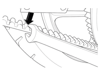
1. Remove the key from the key switch.
Note: The location of the swingarm ground strap and brake line clips, before removing the rear fender.
2. Remove the 4 bolts securing the rear fender to the swingarm, and remove the fender.
3. From the application, click the Tension icon and measure.
4. Confirm the phone’s microphone is ON (if applicable).
5. Hold the phone, so the microphone is as close to the drive belt as possible (without touching the belt).
6. Pluck the belt with your thumb or a wrench (as shown) so that it vibrates like a guitar string.

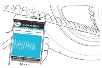
7. The microphone will measure vibration’s frequency.
8. Rotate the rear wheel a quarter-turn and repeat the frequency measurement.
9. Compare your belt’s frequency readings to the recommended range values (see chart above).
Adjustment Procedure
1. Remove the 4 bolts securing the rear fender to the swingarm, and remove the fender.
2. Loosen the rear axle shaft nut (1).
3. Loosen the jam nuts (3), adjust the belt tension by turning the axle adjusters (2) an equal number of turns to keep the wheel aligned until the specification is achieved.
4. Tighten the jam nuts (3).

Notice: Refer to Fastener Notice in General Information.
5. Tighten the axle shaft nut.
Tighten
Axle shaft nut to 102 N•m (75 lb ft)
6. Road test the motorcycle. Refer to Road Testing Procedure.
7. Recheck the belt for proper tension adjustment after the test ride and readjust if necessary.
8. Install the fender onto the swingarm.
10. If the tension is not within specification, the belt will need to be adjusted. Refer to the adjustment procedure below.
Version 1
| Torque settings for: Using Tension Tester Tool | |
| Item | Torque Setting |
| Axle Shaft Nut | 102 N•m (75 lb ft) |
| Axle Adjuster Jam Nut | 20 N•m (15 lb ft) |
 Show Torque Table
Checking Procedure
Required Tools
• Belt Tension Tester
• 3mm hex wrench
• 27mm socket and socket wrench
• 13mm wrench
Fastener Torques
• Axle shaft nut to 102 N•m (75 lb ft)
• Axle adjuster jam nut to 20 N•m (15 lb ft)
The Tension Tester has a plastic measurement arm, located in a slot. Along this slot there is a measuring scale. The point of intersection of the measurement arm and the measuring scale shows the tension of the belt. There is a button (clicking pad) on the upper side of the Tension Tester, where you can secure your finger with a rubber band holder. A spring is located underneath this clicking pad. If a certain pressure is applied to the spring, it makes a clicking sound.

1. Remove the key from the key switch.
2. Press the Tension Tester steadily to the middle of the upper side of the belt. The “lip” will lead the tester to the belt.
3. Slowly increase the pressure on the tester, until you hear a clicking sound. Do not increase the pressure after the tester has clicked.
4. Remove the tester carefully from the belt. Avoid rough movements of the tester, as this would change the results of the measurement. The measurement should be in the range of 20-30 kg.
5. The measurement should be in the range of 20-30 kg. If the tension is not within specification the belt will need to be adjusted. Refer to the adjustment procedure below.
Adjustment Procedure
1. Remove the 4 bolts securing the rear fender to the swingarm, and remove the fender.
2. Loosen the rear axle shaft nut (1).
3. Loosen the jam nuts (3), adjust the belt tension by turning the axle adjusters (2) an equal number of turns to keep the wheel aligned until the specification is achieved.
4. Tighten the jam nuts (3).

Notice: Refer to Fastener Notice in General Information.
5. Tighten the axle shaft nut.
Tighten
Axle shaft nut to 102 N•m (75 lb ft)
6. Road test the motorcycle. Refer to Road Testing Procedure.
7. Recheck the belt for proper tension adjustment after the test ride and readjust if necessary.
8. Install the fender onto the swingarm.
Version 1
| Torque settings for: Chain Replacement | |
| Item | Torque Setting |
| Swingarm Pivot Bolts | 102 N•m (75 lb ft) |
| Swingarm Pivot Bolts | 27 N•m (20 lb ft) |
 Show Torque Table
Required Tools
• 10mm hex wrench
• 3mm hex wrench
• Two 13mm wrenches
• 27mm socket and socket wrench
Fastener Torques
• Swingarm pivot bolts* 102 N•m (75 lb ft)
• Master cylinder bracket bolt to 27 N•m (20 lb ft)
*Use LOCTITE® 242® (or equivalent)
Removal Procedure
1. Raise and safely support the motorcycle.
2. Remove the 4 bolts securing the rear fender to the swingarm, and remove the fender.
3. Loosen the rear axle nut (1).
4. Loosen the chain tensioner jam nut (3) and adjuster bolt (2). Right side shown, left side similar.

5. Slide the wheel forward and remove the chain from the sprocket.
6. Remove the rear master cylinder bracket bolts.
7. Remove the pivot bolt (1). Right side shown, left side similar.
8. Pull the swingarm out enough to remove the chain from the motor pulley.

Installation Procedure
1. Inspect the sprockets for wear or damage, replace as needed.
2. Pull back on the swingarm enough to install the chain on the motor pulley.
Notice: Refer to Fastener Notice in General Information.
3. Install the swingarm pivot bolts (1) and tighten. Right side shown left side similar.
Tighten
Swingarm pivot bolts to 102 N•m (75 lb ft)

4. Install the rear master cylinder bracket bolts.
Tighten
Master cylinder bracket bolts to 27 N•m (20 lb ft)
5. Install the chain on the wheel sprocket.
6. Adjust the chain tension. Refer to Chain Tension Adjustment.
7. Install the fender onto the swingarm.
8. Lower the motorcycle.
Version 1
| Torque settings for: Chain Tension Adjustment | |
| Item | Torque Setting |
| Axle Shaft Nut | 102 N•m (75 lb ft) |
| Axle Adjuster Jam Nut | 20 N•m (15 lb ft) |
 Show Torque Table
Required Tools
• 3mm hex wrench
• 27mm socket and socket wrench
• 13mm wrench
Fastener Torques
• Axle shaft nut to 102 N•m (75 lb ft)
• Axle adjuster jam nut to 20 N•m (15 lb ft)
Checking Procedure
1. Remove the key from the key switch.
2. Have an assistant hold the motorcycle upright with the motorcycles wheels on the ground.
3. Using a ruler, grasp the chain halfway between the front and rear sprockets.
The chain should move 16 mm (0.75 in) in either direction, so 32 mm (1.25 in) of total free play.
4. If the chain’s free play is not within specifications it will need to be adjusted. Refer to the Adjustment Procedure below.

Adjustment Procedure
1. Remove the 4 bolts securing the rear fender to the swingarm, and remove the fender.
2. Loosen the rear axle shaft nut (1).
3. Loosen the jam nuts (3), adjust the belt tension by turning the axle adjusters (2) an equal number of turns to keep the wheel aligned until the specification is achieved.
4. Tighten the jam nuts (3).

Notice: Refer to Fastener Notice in General Information.
5. Tighten the axle shaft nut.
Tighten
Axle shaft nut to 102 N•m (75 lb ft)
6. Road test the motorcycle. Refer to Road Testing Procedure.
7. Recheck the chain for proper tension adjustment after the test ride and readjust if necessary.
8. Install the fender onto the swingarm.
Version 1
| Torque settings for: Rear Drive Sprocket Replacement-Belt | |
| Item | Torque Setting |
| Rear Sprocket Bolts | 35 N•m (26 lb ft) |
| Axle Shaft Nut | 102 N•m (75 lb ft) |
 Show Torque Table
Belt drive shown optional, chain drive similiar.
Required Tools
• 27mm socket and socket wrench
• 5mm hex wrench
Fastener Torques
• Rear sprocket bolts to 35 N•m (26 lb ft)
• Axle shaft nut to 102 N•m (75 lb ft)
Removal Procedure
1. Securely raise and support the motorcycle so that the rear wheel is off the ground.
2. Remove the rear axle nut (1) and tap out the axle shaft (2).
Note: be aware of the axle shaft spacers (REAR WHEEL SPACER RIGHT, REAR WHEEL SPACER LEFT) that are on each side of the wheel.

3. Lower the wheel and remove the drive belt (or chain) from the sprocket.
Important: Support the brake caliper with mechanic's wire, or equivalent, whenever it is separated from its mount and the hydraulic flexible brake hose is still connected. Failure to support the caliper in this manner will cause the flexible brake hose to bear the weight of the caliper, which may cause damage to the brake hose and in turn may cause a brake fluid leak.
4. Move and support the brake caliper with mechanic's wire or equivalent. DO NOT disconnect the hydraulic brake hose from the brake caliper.
5. Remove the 4 Allen bolts (1) and nuts securing the sprocket to the wheel.
6. Remove the rear sprocket (2) (SPROCKET REAR BELT DRIVE 132T, 8MM PITCH, 17MM WIDE CASTING, or, SPROCKET REAR BELT DRIVE 132T, 8MM PITCH, 17MM WIDE FINISHED) from the wheel.

Installation Procedure
Important: Whenever the sprocket has been separated from the wheel flange, any rust or contaminants must be cleaned from the wheel flange and the sprocket mating surfaces. Failure to do this may result in excessive assembled lateral runout (LRO) of the sprocket, which could lead to vibration.
1. Inspect the sprocket and wheel flange surface for rust or contamination. Remove rust or contamination if necessary.
2. Install the sprocket (2) onto the wheel flange.
Notice: Refer to Fastener Notice in General Information.
3. Install the sprocket bolts (1) and nuts. Tighten in a crisscross pattern.
Tighten
Rear sprocket bolts to 35 N•m (26 lb ft)

4. Place the caliper into position on the swingarm.
5. Place the drive belt (or chain) onto the wheel sprocket, ensure that both wheel spacers are in place. Note: the longer spacer is for the left side the shorter is for the right side.
6. Move the wheel into position, ensure that the brake rotor is centered between the brake pads.
7. Slide the axle shaft (2) through the swingarm and wheel and install the nut (1).
Tighten
Axle shaft nut to 102 N•m (75 lb ft)

Version 1
Drive Belt
Proper belt tension is essential for optimum operation of the Gates Carbon Drive System. Lack of belt tension can lead to so-called “ratcheting.“ The teeth of the belt will slide over the teeth of the rear sprocket. This causes not only an unpleasant sound; the ratcheting can also cause damage to the carbon tensile cords. This would render a belt useless. If ratcheting has occurred you should replace the belt before the next time it is to be used. Too much tension can also cause damage to the bearings within the rear hub. It also increases the wear of your drive system and the system can drag.
The belt should be replaced at 40,000 km (25,000 miles).
Drive belt and sprockets do not need lubrication of any kind. For cleaning, use only water and a soft brush. Do not use any type of detergent. Proper handling of the belt is crucial to obtain maximum life expectancy. Bending or twisting of the belt may cause damage to the carbon fibers inside the belt. Avoid the following conditions when handling the belt.

Legend
1. Crimping
2. Twisting
3. Back Bending
4. Inverting
5. Zip Tying
6. Using as a wrench
Version 1
| Torque settings for: Chain Replacement | |
| Item | Torque Setting |
| Swingarm Pivot Bolts | 102 N•m (75 lb ft) |
| Swingarm Pivot Bolts | 27 N•m (20 lb ft) |
 Show Torque Table
Required Tools
• 10mm hex wrench
• 3mm hex wrench
• Two 13mm wrenches
• 27mm socket and socket wrench
Fastener Torques
• Swingarm pivot bolts* 102 N•m (75 lb ft)
• Master cylinder bracket bolt to 27 N•m (20 lb ft)
*Use LOCTITE® 242® (or equivalent)
Removal Procedure
1. Raise and safely support the motorcycle.
2. Remove the 4 bolts securing the rear fender to the swingarm, and remove the fender.
3. Loosen the rear axle nut (1).
4. Loosen the chain tensioner jam nut (3) and adjuster bolt (2). Right side shown, left side similar.

5. Slide the wheel forward and remove the chain from the sprocket.
6. Remove the rear master cylinder bracket bolts.
7. Remove the pivot bolt (1). Right side shown, left side similar.
8. Pull the swingarm out enough to remove the chain from the motor pulley.

Installation Procedure
1. Inspect the sprockets for wear or damage, replace as needed.
2. Pull back on the swingarm enough to install the chain on the motor pulley.
Notice: Refer to Fastener Notice in General Information.
3. Install the swingarm pivot bolts (1) and tighten. Right side shown left side similar.
Tighten
Swingarm pivot bolts to 102 N•m (75 lb ft)

4. Install the rear master cylinder bracket bolts.
Tighten
Master cylinder bracket bolts to 27 N•m (20 lb ft)
5. Install the chain on the wheel sprocket.
6. Adjust the chain tension. Refer to Chain Tension Adjustment.
7. Install the fender onto the swingarm.
8. Lower the motorcycle.
Version 1
| Torque settings for: Chain Tension Adjustment | |
| Item | Torque Setting |
| Axle Shaft Nut | 102 N•m (75 lb ft) |
| Axle Adjuster Jam Nut | 20 N•m (15 lb ft) |
 Show Torque Table
Required Tools
• 3mm hex wrench
• 27mm socket and socket wrench
• 13mm wrench
Fastener Torques
• Axle shaft nut to 102 N•m (75 lb ft)
• Axle adjuster jam nut to 20 N•m (15 lb ft)
Checking Procedure
1. Remove the key from the key switch.
2. Have an assistant hold the motorcycle upright with the motorcycles wheels on the ground.
3. Using a ruler, grasp the chain halfway between the front and rear sprockets.
The chain should move 16 mm (0.75 in) in either direction, so 32 mm (1.25 in) of total free play.
4. If the chain’s free play is not within specifications it will need to be adjusted. Refer to the Adjustment Procedure below.

Adjustment Procedure
1. Remove the 4 bolts securing the rear fender to the swingarm, and remove the fender.
2. Loosen the rear axle shaft nut (1).
3. Loosen the jam nuts (3), adjust the belt tension by turning the axle adjusters (2) an equal number of turns to keep the wheel aligned until the specification is achieved.
4. Tighten the jam nuts (3).

Notice: Refer to Fastener Notice in General Information.
5. Tighten the axle shaft nut.
Tighten
Axle shaft nut to 102 N•m (75 lb ft)
6. Road test the motorcycle. Refer to Road Testing Procedure.
7. Recheck the chain for proper tension adjustment after the test ride and readjust if necessary.
8. Install the fender onto the swingarm.
Version 1
| Torque settings for: Rear Drive Sprocket Replacement-Belt | |
| Item | Torque Setting |
| Rear Sprocket Bolts | 35 N•m (26 lb ft) |
| Axle Shaft Nut | 102 N•m (75 lb ft) |
 Show Torque Table
Belt drive shown optional, chain drive similiar.
Required Tools
• 27mm socket and socket wrench
• 5mm hex wrench
Fastener Torques
• Rear sprocket bolts to 35 N•m (26 lb ft)
• Axle shaft nut to 102 N•m (75 lb ft)
Removal Procedure
1. Securely raise and support the motorcycle so that the rear wheel is off the ground.
2. Remove the rear axle nut (1) and tap out the axle shaft (2).
Note: be aware of the axle shaft spacers (REAR WHEEL SPACER RIGHT, REAR WHEEL SPACER LEFT) that are on each side of the wheel.

3. Lower the wheel and remove the drive belt (or chain) from the sprocket.
Important: Support the brake caliper with mechanic's wire, or equivalent, whenever it is separated from its mount and the hydraulic flexible brake hose is still connected. Failure to support the caliper in this manner will cause the flexible brake hose to bear the weight of the caliper, which may cause damage to the brake hose and in turn may cause a brake fluid leak.
4. Move and support the brake caliper with mechanic's wire or equivalent. DO NOT disconnect the hydraulic brake hose from the brake caliper.
5. Remove the 4 Allen bolts (1) and nuts securing the sprocket to the wheel.
6. Remove the rear sprocket (2) (SPROCKET REAR BELT DRIVE 132T, 8MM PITCH, 17MM WIDE CASTING, or, SPROCKET REAR BELT DRIVE 132T, 8MM PITCH, 17MM WIDE FINISHED) from the wheel.

Installation Procedure
Important: Whenever the sprocket has been separated from the wheel flange, any rust or contaminants must be cleaned from the wheel flange and the sprocket mating surfaces. Failure to do this may result in excessive assembled lateral runout (LRO) of the sprocket, which could lead to vibration.
1. Inspect the sprocket and wheel flange surface for rust or contamination. Remove rust or contamination if necessary.
2. Install the sprocket (2) onto the wheel flange.
Notice: Refer to Fastener Notice in General Information.
3. Install the sprocket bolts (1) and nuts. Tighten in a crisscross pattern.
Tighten
Rear sprocket bolts to 35 N•m (26 lb ft)

4. Place the caliper into position on the swingarm.
5. Place the drive belt (or chain) onto the wheel sprocket, ensure that both wheel spacers are in place. Note: the longer spacer is for the left side the shorter is for the right side.
6. Move the wheel into position, ensure that the brake rotor is centered between the brake pads.
7. Slide the axle shaft (2) through the swingarm and wheel and install the nut (1).
Tighten
Axle shaft nut to 102 N•m (75 lb ft)

Version 1
Drive Belt
Proper belt tension is essential for optimum operation of the Gates Carbon Drive System. Lack of belt tension can lead to so-called “ratcheting.“ The teeth of the belt will slide over the teeth of the rear sprocket. This causes not only an unpleasant sound; the ratcheting can also cause damage to the carbon tensile cords. This would render a belt useless. If ratcheting has occurred you should replace the belt before the next time it is to be used. Too much tension can also cause damage to the bearings within the rear hub. It also increases the wear of your drive system and the system can drag.
The belt should be replaced at 40,000 km (25,000 miles).
Drive belt and sprockets do not need lubrication of any kind. For cleaning, use only water and a soft brush. Do not use any type of detergent. Proper handling of the belt is crucial to obtain maximum life expectancy. Bending or twisting of the belt may cause damage to the carbon fibers inside the belt. Avoid the following conditions when handling the belt.

Legend
1. Crimping
2. Twisting
3. Back Bending
4. Inverting
5. Zip Tying
6. Using as a wrench
Version 1
|
Application
|
Specification
|
|
|
Metric
|
English
|
|
| Steering Stem Lock Nut (inner/lower) | 34 N•m | 25 lb ft |
| Lower Triple Clamp Pinch Bolts | 15 N•m | 11 lb ft |
| Steering Stem Lock Nut (outer/upper) | 81 N•m | 60 lb ft |
| Upper Triple Clamp Pinch Bolts | 81 N•m | 60 lb ft |
| Handlebar Clamp Bolts | 24 N•m | 18 lb ft |
| Front Axle Shaft End Cap Bolts | 26 N•m | 19 lb ft |
| Front Axle Pinch Bolts | 13 N•m | 9.5 lb ft |
| Front Brake Caliper Bolts | 26 N•m | 19 lb ft |
| Headlight Adjuster Bolts | 26 N•m | 19 lb ft |
| Lower Rear Shock Bolts | 52 N•m | 38 lb ft |
| Swingarm Pivot Bolts | 102 N•m | 75 lb ft |
| Rear Axle Shaft Nut | 102 N•m | 75 lb ft |
| Master Cylinder Bracket Bolts | 27 N•m | 20 lb ft |
Version 1
Preliminary Checks
Since problems in steering, suspension, tires, and wheels involve several systems, all systems must be considered when diagnosing a complaint. In order to avoid pursuing the wrong symptom, always test ride the vehicle first. Refer to the Road Testing Procedure. Proceed with the following preliminary checks and correct any substandard conditions which are found.
• Inspect the tires for the following:
- Pressure
- Wear
- Size
- Brand
- Construction
- Balance
- Runout
• Inspect the wheels for the following:
- Size
- Balance
- Runout
- Damage
- Proper installation
• Inspect the following for loose connections, wear, or damage:
- The steering fork
- The front suspension
- The rear suspension
Version 1
| Torque settings for: Steering Head Service | |
| Item | Torque Setting |
| Steering Stem Lock Nut | 34 N•m (25 lb ft) |
| Lower Triple Clamp Pinch Bolts | 15 N•m (11 lb ft) |
| Steering Stem Nut | 81 N•m (60 lb ft) |
| Upper Triple Clamp Pinch Bolts | 23 N•m (17 lb ft) |
| Handlebar Clamp Bolts | 24 N•m (18 lb ft) |
| Front Axle Shaft End Cap Bolts | 26 N•m (19 lb ft) |
| Front Axle Shaft Pinch Bolts | 13 N•m (9.5 lb ft) |
| Front Brake Caliper Bolts | 26 N•m (19 lb ft) |
| Headlight Adjuster Bolts | 26 N•m (19 lb ft) |
 Show Torque Table
Required Tools
• 17mm wrench
• Steering stem lock nut socket
• 16mm hex wrench
• 41mm socket
• 6mm hex wrench
• 5mm hex wrench
• 3mm hex wrench
Replacement Parts
• Lower Triple Clamp Assembly – XMX
Fastener Torques
Notice: Refer to Fastener Notice in General Information.
• Steering stem lock nut (inner/lower) to 34 N•m (25 lb ft)
• Lower triple clamp pinch bolts to 15 N•m (11 lb ft)
• Steering stem nut (outer/upper) to 81 N•m (60 lb ft)
• Upper triple clamp pinch bolts to 23 N•m (17 lb ft)
• Handlebar clamp bolts to 24 N•m (18 lb ft)
• Front axle shaft end cap bolts to 26 N•m (19 lb ft)
• Front axle shaft pinch bolts 13 N•m (9.5 lb ft)
• Front brake caliper bolts to 26 N•m (19 lb ft)
• Headlight Adjuster bolts to 26 N•m (19 lb ft)
*Use LOCTITE® 242® (or equivalent)
Exploded View

Legend:
1. Steering Stem Nut
2. Washer
3. Upper Triple Clamp
5. Dust Seal
6. Bearing and Inner Race
7. Bearing
8. Dust Seal
9. Lower Triple Clamp
Removal Procedure
1. Remove the key from the key switch and support the motorcycle upright on a stand with the front wheel off the ground.
2. Remove the 2 caliper bolts (1). Support the brake caliper (2) with mechanic's wire, or equivalent, whenever it is separated from its mount and the hydraulic flexible brake hose is still connected. Failure to support the caliper in this manner will cause the flexible brake hose to bear the weight of the caliper, which may cause damage to the brake hose and in turn may cause a brake fluid leak.

3. Slide the brake caliper off of the brake rotor and support the brake caliper with mechanic's wire or equivalent. DO NOT disconnect the hydraulic brake hose from the brake caliper.
4. Remove the front axle end cap bolt (2) and end cap (3) on the right side.
5. Remove the front axle shaft pinch bolts (1).
6. Slide the front axle shaft out of the fork on the left side, and remove the tire. Do not lose the wheel spacers (4).

7. Remove the front fender.
8. Remove the fly screen bolts (1) and the fly screen.
9. Remove the lower headlight bolts (2) from both sides and move the headlight off to the side.

10. Remove the headlight/turn signal bracket bolts (1) from both sides.

11. Remove handlebar bolts (1), clamps, and the handlebar. Lay forward along with the turn signals and instrument panel assembly.
12. Loosen the upper triple clamp pinch bolts.
13. Remove steering stem nut and washer (2).

14. Remove upper triple clamp. Place towel between triple clamp and handlebar for protection.
15. Loosen the lower triple clamp pinch bolts.
16. Remove both of the forks (FX FORK SET FASTACE 14MY, MY14 FX LEFT FORK LEG, MY14 FX RIGHT FORK LEG) from lower triple clamp.
17. Using a steering stem nut socket (1), remove steering stem lock nut.

18. Remove lower triple clamp assembly from frame.
19. Remove all bearings and dust seals.

Inspection Procedure
1. Clean head tube bore completely.
2. Clean bearing races and steering stem with brake cleaner or alcohol.
3. Inspect steering stem just above the lower inner race for scoring/gouging of steering stem.
If you find scoring or damage to the steering stem, you must replace the lower triple clamp assembly, bearings, and races. If the bearing races are loose in the head tube bores, the frame must be replaced.
If scoring/pitting or any other damage is found on the bearings or races, the bearing and races must be replaced.
Bearing Race Replacement
Removal Procedure
The bearing race is pressed into the head tube bore. To remove the race, insert a soft punch into the head tube and carefully tap the race out from the inside. There are notches (1) in the head tube for the punch, to get the race started. After it is started, tap around the race to get it out evenly without damaging the head tube bore.
Note: When the race is removed it can score the head tube bore. Inspect the head tube bore area (2) for any damage. If any damage is found, smooth bore with 600 grit sandpaper to remove scores or ridges.

Installation Procedure
1. Apply Loctite® 609® to sides and bottom of outer race and sides and bottom of head tube bore.
2. Tap the race in slowly and evenly with a race installer or suitable socket. Make sure that the race is squarely seated in the head set bore before tapping it in. Ensure that the race is fully seated in the head tube bore.
3. Wipe residual green Loctite® 609® from race and head tube.
Installation Procedure
1. Fully pack the bearings with grease. You MUST thoroughly work the grease into the bearings, between the rollers, the core and the cage.
2. Install the lower dust seal (1) on the steering stem.
3. Apply Loctite® 609® to steering stem (2) and inner race.
4. Slip the inner race (3) onto stem and rotate 2 full turns to evenly distribute Loctite.

5. Wipe clean any residual Loctite.
6. Install upper bearing (1) and upper inner race (2) into top head tube bore.

7. Install the upper dust seal (1).

8. Install lower bearing (1) onto the steering stem.

9. Install lower triple clamp assembly into head tube.
Note: Install steering stem lock nut with bevel side down. Take care to keep centered, upward force on lower triple clamp while installing steering stem lock nut so that it is hand-tight. Rotate lower triple clamp and feel for smooth rotation.
Notice: Refer to Fastener Notice in General Information.
10. Using a steering stem lock nut socket tighten the steering stem lock nut to 68 N•m (50 lb ft) and then back off the nut so that it is hand-tight.
11. Then tighten the steering stem lock nut.
Tighten
Steering stem lock nut to 34 N•m (25 lb ft)
12. Rotate lower triple clamp assembly and feel for smooth rotation again.
13. Install upper triple clamp onto steering stem.
14. Check that the routing of brake lines and harness is correct.
15. Install the top washer and nut onto steering stem and leave loose.
16. Install forks into the triple clamps.
17. Set the top of forks 10mm (A) from the top of upper triple clamp bore.

18. Tighten the lower triple clamp pinch bolts.
Tighten
Lower triple clamp bolts to 15 N•m (11 lb ft)
19. Tighten the steering stem nut (2).
Tighten
Steering stem nut to 81 N•m (60 lb ft)
20. Tighten the upper triple clamp pinch bolts.
Tighten
Upper triple clamp pinch bolts to 23 N•m (17 lb ft)
21. Install the handlebar, clamps and bolts (1).
Tighten
Handlebar clamp bolts to 24 N•m (18 ft lb)

22. Install the headlight/turn signal brackets and bolts (1) for both sides.

23. Install headlamp and adjuster bolts.
24. Install the fly screen, ensure that ground C239 is between the fly screen bolts (1) and the bracket.

25. Install the front fender.
26. Position the wheel onto the motorcycle.
27. Slide the front axle shaft through both fork legs and the wheel, making sure that the spacers (4) are in place. There is one spacer for each side of the axle shaft.
28. Apply LOCTITE® 242® to the threads of the axle end cap bolt.
29. Install the axle end cap (3) and end cap bolt (2).
Tighten
Axle end cap bolts to 26 N•m (19 lb ft)
30. Apply LOCTITE® 242® to the front axle pinch bolts (1).
31. Install the front axle pinch bolts (1).
Tighten
Front axle shaft pinch bolts 13 N•m (9.5 lb ft)

32. Install the front brake caliper (2) and bolts (1). Ensure that the disc brake pads are centered on the brake rotor.
Tighten
Front brake caliper bolts to 26 N•m (19 lb ft)

33. Let the motorcycle sit for no less than 12 hours to allow Loctite to cure.
34. Adjust the headlight. Refer to Headlight Adjustment.
36. Road test the motorcycle to ensure that the condition has been corrected. Refer to Road Testing Procedure.
Version 1
Front Fork Adjustment
1. Bleed Screw
The 3mm Allen screw (1) at the top of the fork leg is the “bleed” screw. The bleed screw serves two purposes:
• Transporting the motorcycle. To let air out when the fork is compressed during transporting.
• Bleeding the fork: Bleed the fork regularly, let any excess air out after each ride.
2. Rebound Damping
The rebound damping is adjusted by turning the slotted brass adjuster screw (2) on the top of both fork legs. Next to it will be the writing S-F, meaning Slow and Fast. The adjuster has 14 stages of adjustment. This determines how quickly the fork returns to its extended position after being compressed. Turning the rebound adjuster screw clockwise will slow the rebound speed down making it better for larger, rolling terrain or bumps. Turning the rebound adjuster screw counter-clockwise will increase the rebound speed making it better for smaller, rougher bumps. Adjust each fork leg evenly.

3. Compression Damping
The compression damping is adjusted by turning a screw on the bottom of each fork leg. There is a rubber dust cover protecting the screw (2) and a jam nut (1) securing the screw. The adjuster has 10 stages of adjustment. Turn the adjuster clockwise for slower compression. To speed up compression, turn the adjuster counter-clockwise. Start with a middle setting and fine tune the compression from there. Proper compression will allow the tire to track the ground over consecutive bumps. Compression that is set too slow will pack-up (feel harsh over consecutive bumps) while compression that is set too fast will cause the fork to bottom out harshly. If the fork is bottoming out, turn the adjuster one turn at a time until the bottoming-out stops. Adjust each fork leg evenly. Replace the rubber dust cover after the adjustment.

Rear Shock Adjustment
Spring Adjustment:
Obtaining the correct rear spring rate is critical for proper handling. The spring rate must be set to match the weight of the rider. The spring is preloaded for an 82 kg (180 lb) rider. This puts the rear tire 1/3 of the way through it's vertical travel. Heavier riders require stiffer spring rates. A good approximation of the rear spring requirements can be found by measuring the rear suspension’s sag. This measurement will quickly determine if the rear spring is approximately correct for the rider's weight. This adjustment is a recommendation guideline; personal riding preference may vary from the specifications given.
• Checking Sag
1. Support the motorcycle on a stand with the rear wheel off the ground.
2. Measure vertically from the rear axle to the rear fender; mark this spot as it will be used for other measurements.
3. Record this measurement, this will be measurement M1.

4. Remove the motorcycle from the stand.
5. Wearing normal riding apparel, sit on the motorcycle.
6. Have an assistant hold the motorcycle up, your feet should be on both pegs.
7. Bounce the suspension a couple of times.
8. Have a second assistant take a measurement using the same locations as in step 2.
9. Record this measurement, this will be measurement M2.

10. Subtract the second measurement (M2) from the first measurement (M1).
Example:
|
M1
|
|
600 mm (23.62 in)
|
|
M2
|
-
|
550 mm (21.65 in)
|
|
Sag
|
=
|
50 mm (1.97 in)
|
The total sag (in example above) is 1.97 in (50 mm). The recommended total sag is 2.3 in to 2.9 in (69-76 mm). If the sag is not correct, the spring pre-load should beadjusted. Refer to Spring Pre-load Adjustment below.
| MODEL | SAG |
| FX | 74 mm (69-762.9 in) |
Spring Pre-load Adjustment
1. Clean any dirt or debris from the threads of the lock ring (1).
2. Using a lock ring wrench loosen the lock nut (1).
3. For measurements less than the specified value, decrease the pre-load on the spring by turning the spring nut (2) counter-clockwise on the shock. If more than the specified value, increase the pre-load on the spring by turning the spring nut (2) clockwise on the shock.
4. Recheck the sag. If the sag is correct, tighten the lock nut (1).

Rebound Adjustment
The rebound adjuster (1) is at the bottom of the shock. It has 12 stages of adjustment. Printed on the shock is S-F, meaning Slow and Fast. The rebound adjuster controls how slow or fast the shock returns to its extended position after being compressed. Turning the adjuster clockwise, or S direction, is good for big impacts. Turning the adjuster counter-clockwise, or F direction, is good for many smaller and more frequent impacts.

Compression Adjustment
The compression adjustment knob is under the rear of the seat. It has 16 stages of adjustment. The knob has HARD (slower compression) and SOFT (faster compression). Turn the adjuster clockwise for slower compression. To speed up compression, turn the adjuster counter-clockwise. Start with a middle setting and fine tune the compression from there. Proper compression will allow the tire to track the ground over consecutive bumps. Compression that is set too slow will pack-up (feel harsh over consecutive bumps) while compression that is set too fast will cause the shock to bottom out harshly. If the shock is bottoming out, turn the adjuster one click at a time until the bottom out stops.
Note: Adjusters should never be forced completely "Soft" or "Hard" always leave one click of adjustment in either direction.

Version 1
| Torque settings for: Swingarm Assembly Replacement | |
| Item | Torque Setting |
| Swingarm Pivot Bolts | 102 N•m (75 lb ft) |
| Axle Shaft Nut | 102 N•m (75 lb ft) |
| Lower Rear Shock Nut And Bolt | 52 N•m (38 lb ft) |
| Master Cylinder Bracket Bolt | 27 N•m (20 lb ft) |
 Show Torque Table
Required Tools
• 3mm hex wrench
• 10mm hex wrench
• 27mm socket
• Socket wrench
• 15mm wrench
• 13mm wrench
• 17mm wrench
Fastener Torques
• Swingarm pivot bolts* 102 N•m (75 lb ft)
• Lower shock nut and bolt 52 N•m (38 lb ft)
• Master cylinder bracket bolt to 27 N•m (20 lb ft)
• Axle shaft nut to 102 N•m (75 lb ft)
*Use LOCTITE® 242® (or equivalent)
Removal Procedure
1. Remove the 4 bolts securing the rear fender to the swingarm, and remove the fender.
2. Securely raise and support the motorcycle so that the rear wheel is off the ground.
3. Remove the rear axle nut (1) and tap out the axle shaft (2). Note that there are axle shaft spacers (REAR WHEEL SPACER RIGHT, REAR WHEEL SPACER LEFT) that are on each side of the wheel. The longer spacer is for the left side and the shorter is for the right side.

4. Lower the wheel and remove the drive belt (or chain) from the sprocket.
Important: Support the brake caliper with mechanic's wire, or equivalent, whenever it is separated from its mount and the hydraulic flexible brake hose is still connected. Failure to support the caliper in this manner will cause the flexible brake hose to bear the weight of the caliper, which may cause damage to the brake hose and in turn may cause a brake fluid leak.
5. Move and support the brake caliper with mechanic's wire or equivalent. DO NOT disconnect the hydraulic brake hose from the brake caliper.
6. Remove the rear master cylinder bracket bolts.
7. Remove the shock lower nut and bolt.
8. Remove the swing arm pivot bolt (1). Right side shown, left side similar.
9. Remove the swingarm assembly.

Installation Procedure
1. Place the swingarm assembly into position.
Notice: Refer to Fastener Notice in General Information.
2. Install the swingarm pivot bolts (1) and tighten. Right side shown, left side similar.
Tighten
Swingarm pivot bolts to 102 N•m (75 lb ft)

3. Install the shock lower nut and bolt.
Tighten
Shock nut and bolt to 52 N•m (38 lb ft)
4. Install the rear master cylinder bracket bolts.
Tighten
Master cylinder bracket bolt to 27 N•m (20 lb ft)
5. Place the caliper into position on the swingarm.
6. Place the drive belt (or chain) onto the wheel sprocket. Ensure that both wheel spacers are in place.
7. Move the wheel into position, ensuring that the brake rotor is centered between the brake pads.
8. Slide the axle shaft (2) through the swingarm and wheel and install the nut (1).
Tighten
Axle shaft nut to 102 N•m (75 lb ft)
9. Install the fender onto the swingarm.

Version 1
Description and Operation
The front and rear suspension can be adjusted for sag and damping, for adjustment procedures refer to Suspension Adjustment.
Front Suspension
The fork assembly contains the triple tree and fork legs (shocks). The triple tree holds the fork legs in place and attaches the fork assembly to the frame.
The shock has two main actions: Compression when the shock gets compressed, and rebound when the shock returns back to full length. Compression damping is the adjustment that determines how fast or slow the fork compresses. Rebound damping is the adjustment that determines how fast or slow the fork rebounds.
Front Fork Adjustments
|
ADJUSTMENT
|
SETTING
|
|
Front Fork Compression
|
10 clicks out from fully closed
|
|
Front Fork Rebound
|
14 clicks out from fully closed
|
Rear Suspension
The rear suspension is a swingarm with a monoshock design. One end of the swingarm is connected to the frame (pivot end) and the other end to the wheel. Controlling the action/movement of the swingarm is the shock.
The shock is a fully adjustable coilover design. The coilover shock contains a spring surrounding it. The spring rate is adjustable. The rate is a measure of how much force is required to compress the spring a given distance. The higher the rate, the more force it takes to compress it a given distance, and the less it compresses under a given force.
The shock has two main actions: Compression when the shock gets compressed, and rebound when the shock returns back to full length. Compression damping is the adjustment that determines how fast or slow the shock compresses. Rebound damping is the adjustment that determines how fast or slow the shock rebounds.
Rear Sag Adjustment
|
MODEL
|
SAG
|
|
FX
|
69-76 mm (2.3-2.9 in)
|
Version 1
|
Application
|
Specification
|
|
|
Metric
|
English
|
|
|
Axle End Cap Bolts
|
26 N•m
|
19 lb ft
|
| Front Axle Pinch Bolts |
13 N•m
|
9.5 lb ft
|
|
Brake Bleeder Valves
|
7 N•m
|
62 lb in
|
|
Brake Hose Banjo Bolt
|
27 N•m
|
20 lb ft
|
|
Front Brake Caliper Bolts
|
26 N•m
|
19 lb ft
|
|
Front Brake Rotor Bolts
|
13 N•m
|
9.5 lb ft
|
|
Rear Brake Caliper Slide Pin
|
XX N•m
|
XX lb ft
|
|
Rear Axle Shaft Nut
|
102 N•m
|
75 lb ft
|
|
Rear Brake Rotor Bolts
|
13 N•m
|
9.5 lb ft
|
Version 1
|
Causes |
Correction |
| Sticky caliper or caliper pistons | Replace the caliper. |
| Contaminated or improper brake fluid | Flush the brake system and repair the affected brake components. |
| Loose front or rear brake assembly components | Locate and tighten the loose brake components. |
| Brake lever/pedal binding | Repair or replace the brake lever/pedal. |
Version 1
|
Causes |
Correction |
| Leaking brake hose or connection | Locate and repair the brake hose or the connection. |
| Leaking caliper piston seal | Replace the caliper. |
| Leaking master cylinder (internally) | Replace the master cylinder. |
Version 1
|
Cause |
Correction |
| Linings damaged by abusive use | Replace the brake linings. |
| Poor rotor surface finish | Replace the rotor. |
Version 1
|
Causes |
Correction |
| Worn-out brake linings | Replace the brake linings. |
| Incorrect lining material | Replace the brake linings. |
| Contaminated brake linings | Replace the brake linings. |
| Linings damaged by abusive use | Replace the brake linings. |
| Scored rotor | Replace the rotor. Inspect and replace brake linings if necessary. |
Version 1
|
Causes |
Correction |
| Loose front suspension parts | Locate and tighten, repair or replace the loose front suspension components. |
| Worn-out brake linings | Replace the brake linings. |
| Uneven brake lining material | Replace the brake linings. |
| Contaminated brake linings | Replace the brake linings. |
| Linings damaged by abusive use | Replace the brake linings. |
Scraping Noise
|
Causes |
Correction |
| Loose front suspension parts | Locate and tighten, repair or replace the loose front suspension components. |
| Worn-out brake linings | Replace the brake linings. |
| Contaminated brake lining | Replace the brake linings. |
| Linings damaged by abusive use | Replace the brake linings. |
| Front or rear brake assembly components loose | Locate and tighten the loose brake components. |
Chatter/Roughness
|
Causes |
Correction |
| Scored rotor | Replace the rotor. Inspect and replace brake linings if necessary. |
| Improper thickness variation in rotor | Replace the rotor. |
| Excessive rotor lateral runout | Replace the rotor. |
| Loose front or rear brake assembly components | Locate and tighten the loose brake components. |
Version 1
|
Causes |
Correction |
| Contaminated or improper brake fluid | Flush the brake system and repair the affected brake components. |
| Sticky caliper pistons | Replace the caliper. |
Version 1
|
Causes |
Correction |
| Glazed brake linings | Replace the brake linings. |
| Worn-out brake linings | Replace the brake linings. |
| Incorrect lining material | Replace the brake linings. |
| Contaminated brake linings | Replace the brake linings. |
| Linings damaged by abusing use | Replace the brake linings. |
| Restricted brake fluid passage | Locate and repair the brake fluid passage restriction. |
| Brake lever/pedal interference or binding | Repair or replace the brake lever/pedal. |
Version 1
|
Causes |
Correction |
| Air in the brake system | Bleed the brake system. |
| Leaking brake hose or connection | Locate and repair the brake hose or the connection. |
| Leaking caliper piston seal | Replace the caliper. |
| Leaking master cylinder (internally) | Replace the master cylinder. |
| Contaminated/improper brake fluid | Flush the brake system and repair the affected brake components. |
| Loose front or rear brake assembly components | Locate and tighten loose brake components. |
Version 1
| Torque settings for: Brake Pad Replacement-Front | |
| Item | Torque Setting |
| Front Brake Caliper Bolts | 26 N•m (19 lb ft) |
 Show Torque Table
Required Tools
• Flat blade screwdriver
• 13mm wrench
Fastener Torques
• Front brake caliper bolts to 26 N•m (19 lb ft)
Removal Procedure
1. Remove the 2 caliper bolts (1).
Important: Support the brake caliper with mechanic's wire, or equivalent, whenever it is separated from its mount, and the hydraulic flexible brake hose is still connected. Failure to support the caliper in this manner will cause the flexible brake hose to bear the weight of the caliper, which may cause damage to the brake hose and in turn may cause a brake fluid leak.
2. Slide the brake caliper off of the brake rotor and support the brake caliper with mechanic's wire or equivalent. DO NOT disconnect the hydraulic brake hose from the brake caliper.
Important: To prevent dirt and other contaminants from entering the master cylinder, thoroughly clean the cover before removal.
3. Remove the two screws to release the cover from the front master cylinder reservoir.
Note: As the pistons are pushed back into the caliper, the fluid level may rise and overflow the reservoir. Watch the fluid level as the pistons are retracted and remove fluid from the reservoir if necessary.
4. Press in the inner and outer brake pads pushing the pistons back into their bores.
5. Remove the caliper slide pin (2), and remove the pads from the caliper.
6. Inspect the brake caliper and brake hardware and replace as needed.

Installation Procedure
1. Install the disc brake pads to the brake caliper, making sure that the anti-rattle clip is in position.
2. Install the disc brake pads into the caliper.
3. Install the caliper slide pin (2) and tighten.
4. Slide the brake caliper onto the rotor, making sure that the disc brake pads are centered on the brake rotor.
Notice: Refer to Fastener Notice in General Information.
5. Install the front caliper bolts (1).
Tighten
Front brake caliper bolts to 26 N•m (19 lb ft)
Caution: After installation of new pads, and before moving motorcycle, pump the front brake lever to build brake system pressure. Insufficient pressure can adversely affect brake performance, which could result in death or serious injury.
6. Verify that brake fluid level is full. Add brake fluid, if necessary.
7. Install master cylinder reservoir cover.
Caution: After completing repairs or bleeding the system, always test motorcycle brakes at low speed. If brakes are not operating properly or braking efficiency is poor, testing at a high speed could result in death or serious injury.
8. Road test the motorcycle; refer to Road Testing Procedure. If the brakes feel spongy, bleed the system.

Version 1
| Torque settings for: Brake Pad Replacement-Rear | |
| Item | Torque Setting |
| Axle Shaft Nut | 102 N•m (75 lb ft) |
 Show Torque Table
Required Tools
• 27mm socket and socket wrench
• 5mm Hex wrench
Fastener Torques
• Brake caliper slide pin XX N•m (XX lb ft)
• Axle shaft nut to 102 N•m (75 lb ft)
Caution: Always replace brake pads in pairs. Never replace just one brake pad. Mismatched brake pads can lead to brake system damage and loss of braking performance, which could result in serious injury or death.
1. Securely raise and support the motorcycle so that the rear wheel is off the ground.
2. Remove the rear axle nut (1) and tap out the axle shaft (2). Note: be aware of the axle shaft spacers (REAR WHEEL SPACER RIGHT, REAR WHEEL SPACER LEFT) that are on each side of the wheel.

3. Lower the wheel and remove the drive belt from the sprocket (SPROCKET REAR BELT DRIVE 132T, 8MM PITCH, 17MM WIDE FINISHED, or, SPROCKET REAR BELT DRIVE 132T, 8MM PITCH, 17MM WIDE CASTING).
Important: Support the brake caliper with mechanic's wire, or equivalent, whenever it is separated from its mount and the hydraulic flexible brake hose is still connected. Failure to support the caliper in this manner will cause the flexible brake hose to bear the weight of the caliper, which may cause damage to the brake hose and in turn may cause a brake fluid leak.
4. Move and support the brake caliper with mechanic's wire or equivalent. DO NOT disconnect the hydraulic brake hose from the brake caliper.
5. Remove the caliper slide pin (1).
Important: To prevent dirt and other contaminants from entering the master cylinder, thoroughly clean the cover before removal.
6. Remove the brake fluid reservoir cap from the reservoir.
7. Note: As the piston is pushed back into the caliper, fluid level may rise and overflow the reservoir. Watch the fluid level as the piston is retracted and remove fluid from the reservoir if necessary.
8. Press in the inner and outer brake pads pushing the piston back into the bore.
9. Remove the disc brake pads from the brake caliper.
10. Inspect the brake caliper and brake hardware and replace as needed.

Installation Instructions
1. Install the disc brake pads into the brake caliper, making sure that the anti-rattle clip is in position.
Notice: Refer to Fastener Notice in General Information.
2. Install the caliper slide pin (1).
Tighten
Brake caliper slide pin to XX N•m (XX lb ft)

3. Place the caliper into position on the swingarm.
4. Place the drive belt onto the wheel sprocket, ensuring that both wheel spacers are in place. Note: The longer spacer is for the left side the shorter is for the right side.
5. Move the wheel into position. Ensure that the brake rotor is centered between the brake pads.
6. Slide the axle shaft (2) through the swingarm and wheel and install the nut (1).
Tighten
Axle shaft nut to 102 N•m (75 lb ft)

Caution: After installation of new pads and before moving motorcycle, pump the rear brake pedal to build brake system pressure. Insufficient pressure can adversely affect brake performance, which could result in death or serious injury.
7. Verify that brake fluid level is full. Add brake fluid, if necessary.
8. Install master cylinder reservoir cap.
Caution: After completing repairs or bleeding the system, always test motorcycle brakes at low speed. If brakes are not operating properly or braking efficiency is poor, testing at a high speed could result in death or serious injury.
9. Road test the motorcycle; refer to Road Testing Procedure. If the brakes feel spongy, bleed the system.
Version 1
| Torque settings for: Brake Caliper Replacement-Front | |
| Item | Torque Setting |
| Banjo Bolt | 27 N•m (20 lb ft) |
| Caliper Bleeder Valve | 7 N•m (62 lb in) |
 Show Torque Table
Required Tools
• 13mm wrench
• 8mm wrench
Fastener Torques
• Banjo bolt 27 N•m (20 lb ft)
• Caliper bleeder valve 7 N•m (62 lb in)
Removal Procedure
1. Remove the brake pads. Refer to Brake Pad Replacement-Front.
Notice: Refer to Brake Fluid Effects on Paint and Electrical Components Notice in General Information.
2. Remove the front brake hose banjo bolt (1) and sealing washers (2) from the caliper.
3. Drain the brake fluid into an approved container.

Installation Procedure
Important: Always use new sealing washers on the banjo fittings.
Notice: Refer to Fastener Notice in General Information.
1. Install the front brake hose to the caliper with the banjo bolt (1) and new sealing washers (2).
Tighten
Banjo bolt to 27 N•m (20 lb ft)
2. Install the brake pads. Refer to Brake Pad Replacement-Front.
3. Bleed the front brake system.
4. Road test the motorcycle. Refer to Road Testing Procedure.

Version 1
| Torque settings for: Brake Caliper Replacement-Rear | |
| Item | Torque Setting |
| Banjo Bolt | 27 N•m (20 lb ft) |
| Axle Shaft Nut | 102 N•m (75 lb ft) |
| Caliper Bleeder Valve | 7 N•m (62 lb in) |
 Show Torque Table
Required Tools
• 27mm socket
• 5mm hex wrench
• 8mm hex wrench
• 14mm wrench
Fastener Torques
• Banjo bolt 27 N•m (20 lb ft)
• Caliper bleeder valve 7 N•m (62 lb in)
• Axle shaft nut 102 N•m (75 lb ft)
Removal Procedure
1. Remove the brake pads. Refer to Brake Pad Replacement-Rear.
Notice: Refer to Brake Fluid Effects on Paint and Electrical Components Notice in Cautions and Notices.
2. Slide the caliper off of the caliper bracket.
3. Remove the rear brake hose banjo bolt (1) and sealing washers (2) from the caliper.
4. Drain the brake fluid into an approved container.

Installation Procedure
1. Slide the caliper onto the caliper bracket.
Important: Always use new sealing washers on the banjo fittings.
Notice: Refer to Fastener Notice in General Information.
2. Install the rear brake hose to the caliper with the banjo bolt (1) and new sealing washers (2).
Tighten
Banjo bolt to 27 N•m (20 lb ft)
3. Install the brake pads. Refer to Brake Pad Replacement-Rear.
4. Bleed the rear brake system.
5. Road test the motorcycle. Refer to Road Testing Procedure.

Version 1
| Torque settings for: Brake Rotor Replacement-Front | |
| Item | Torque Setting |
| Front Rotor Bolts | 13 N•m (9.5 lb ft) |
| Axle Pinch Bolts | 13 N•m (9.5 lb ft) |
| Axle End Cap Bolts | 26 N•m (19 lb ft) |
 Show Torque Table
Required Tools
• 5mm hex wrench
• 6mm hex wrench
Fastener Torques
• Front rotor bolts to 13 N•m (9.5 lb ft)
• Axle pinch bolts to 13 N•m (9.5 lb ft)
• Axle end cap bolt to 26 N•m (19 lb ft)
Removal Procedure
1. Remove the front wheel.
• Raise and support the motorcycle.
• Remove the front axle end cap bolt (2) and end cap (3) on the right side.
• Remove the front axle shaft pinch bolts (1).
• Slide the front axle shaft out of the fork on the left side.

2. Remove the 4 Allen bolts (1) securing the rotor to the wheel.
3. Remove the front brake rotor (2) from the wheel.

Installation Procedure
Important: Whenever the rotor has been separated from the wheel flange, any rust or contaminants must be cleaned from the wheel flange and the rotor mating surfaces. Failure to do this may result in excessive assembled lateral runout (LRO) of the brake rotor, which could lead to brake pulsation.
1. Inspect the rotor and wheel flange surface for rust or contamination. Remove rust or contamination if necessary. Clean all fastener threads of LOCTITE®, oil, or grease.
2. Install the brake rotor (2) onto the wheel flange; make sure that the countersunk portion of the brake rotor is facing out.

Notice: Refer to Fastener Notice in General Information.
3. Install the rotor bolts (1) and tighten into the flange.
Tighten
Tighten the front rotor bolts to 13 N•m (9.4 lb ft)
4. Install the front wheel.
• Position the wheel onto the motorcycle and ensure that the brake pads are on each side of the brake rotor.
• Slide the front axle shaft through both fork legs and the wheel, making sure that the spacers (4) are in place. There is one spacer for each side of the axle shaft.
• Apply LOCTITE® 242® to the threads of the axle end cap bolt.
• Install the axle end cap (3) and end cap bolt (2).
Tighten
Axle end cap bolt to 26 N•m (19 lb ft)
• Apply LOCTITE® 242® to the threads of the axle end cap bolt.
• Tighten the front axle pinch bolts (1).
Tighten
Axle pinch bolts to 13 N•m (9.5 lb ft)
5. Road test the motorcycle. Refer to Road Testing Procedure.

Version 1
| Torque settings for: Brake Rotor Replacement-Rear | |
| Item | Torque Setting |
| Rear Brake Rotor Bolts | 13 N•m (9.5 lb ft) |
| Axle Shaft Nut | 102 N•m (75 lb ft) |
 Show Torque Table
Required Tools
• 5mm hex wrench
• 27mm socket and socket wrench
Fastener Torques
• Rear brake rotor bolts 13 N•m (9.5 lb ft)
• Rear axle shaft nut 102 N•m (75 lb ft)
Removal Procedure
1. Remove the rear wheel.
• Securely raise and support the motorcycle so that the rear wheel is off the ground.
• Remove the rear axle nut (1) and tap out the axle shaft. Note that there are axle shaft spacers (REAR WHEEL SPACER RIGHT, REAR WHEEL SPACER LEFT) on each side of the wheel. The longer spacer is for the left side and the shorter is for the right side.
• Lower the wheel and remove the drive belt from the sprocket (SPROCKET REAR BELT DRIVE 132T, 8MM PITCH, 17MM WIDE FINISHED, or, SPROCKET REAR BELT DRIVE 132T, 8MM PITCH, 17MM WIDE CASTING).

Important: Support the brake caliper with mechanic's wire, or equivalent, whenever it is separated from its mount and the hydraulic flexible brake hose is still connected. Failure to support the caliper in this manner will cause the flexible brake hose to bear the weight of the caliper, which may cause damage to the brake hose and in turn may cause a brake fluid leak.
2. Move and support the brake caliper with mechanic's wire or equivalent. DO NOT disconnect the hydraulic brake hose from the brake caliper.
3. Remove the 4 Allen bolts (1) securing the rotor to the wheel.
4. Remove the rear brake rotor (2) (BRAKE ROTOR 240MM FIXED, BRAKE ROTOR 240MM FIXED WITH COUNTERBORE) from the wheel.

Installation Procedure
Important: Whenever the rotor has been separated from the wheel flange, any rust or contaminants must be cleaned from the wheel flange and the rotor mating surfaces. Failure to do this may result in excessive assembled lateral runout (LRO) of the brake rotor, which could lead to brake pulsation.
1. Inspect the rotor and wheel flange surface for rust or contamination. Remove rust or contamination if necessary. Clean all fastener threads of LOCTITE®, oil, or grease.
2. Install the brake rotor (2) onto the wheel flange; make sure that the countersunk portion of the brake rotor is facing out.
Notice: Refer to Fastener Notice in General information.
3. Install the rotor bolts (1) and tighten into the flange.
Tighten
Rear brake rotor bolts to 13 N•m (9.5 lb ft)

4. Install the rear wheel.
• Place the drive belt onto the wheel sprocket, ensure that both wheel spacers are in place.
• Position the wheel onto the motorcycle and ensure that the brake pads are on each side of the brake rotor.
• Slide the axle shaft (2) through the swingarm and wheel and install the nut (1).
Tighten
Axle shaft nut to 102 N•m (75 lb ft)
5. Road test the motorcycle. Refer to Road Testing Procedure.

Version 1
Hydraulic Brake System Description and Operation
General Information
Bleed the hydraulic brake system any time a brake hose, master cylinder or brake caliper has been opened or disassembled, or whenever the brake lever operation feels "spongy." Bleeding evacuates air from the system leaving only incompressible hydraulic fluid. This system requires a special bleeding procedure.
Caution: Use only fresh, uncontaminated DOT 4 brake fluid. Fluid containers that have been opened may have been contaminated by dirt or moisture. Use of contaminated brake fluid may adversely affect braking ability and lead to brake failure which could result in death or serious injury.
Notice: Cover adjacent surfaces when removing, draining, filling and/or bleeding brake system components. Spilling brake fluid on painted or other finished surfaces can result in cosmetic damage. Immediately wipe up any spilled brake fluid and thoroughly clean affected area.
System Component Description
The hydraulic brake system consists of the following:
Hydraulic Brake Master Cylinder
• Contains the supply of brake fluid for the hydraulic brake system.
• Converts mechanical input force (brake lever/pedal) into hydraulic output pressure.
The amount of stroke required for this stage will depend of the amount of clearance between the pads and disc.
• Modulation
The brake pads are now clamping the rotor and by stroking the lever further, additional brake power will be generated.
Hydraulic Brake Flexible Hoses
Carry brake fluid to and from hydraulic brake system components.
Hydraulic Brake Wheel Apply Components
Convert hydraulic input pressure into mechanical output force.
System Operation
The front brake is controlled by a hand-operated master cylinder located on the right handlebar. The rear brake is controlled by a foot-operated master cylinder next to the right foot peg. The master cylinder converts mechanical force into hydraulic pressure. Brake flexible hoses form the hydraulic brake wheel circuits and deliver the hydraulic pressure to the brake calipers. The brake calipers convert the hydraulic pressure into mechanical force which presses linings against rotating brake rotors.
Version 1
1. Double click the desktop icon to start the program.


2. If everything is connected properly and the motorcycle is keyed ON, the ZDU program window will open.
3. Select the “Motor Controller Interface” tab at the top of the window.
Buttons Tab
4. Select the “Buttons” tab in the middle of the page. Then select the “Initialize Device” button.

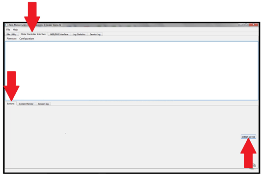
5. Once Initialized, new button selections are available.

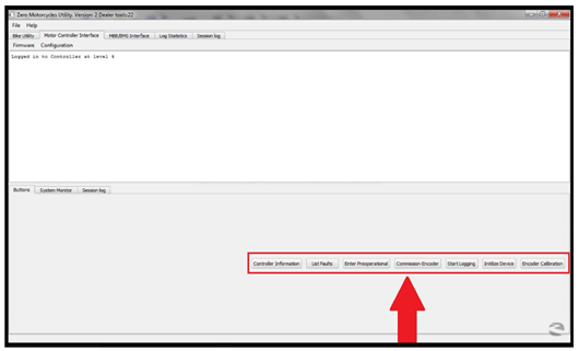
The buttons that we will focus on are as follows:
• Controller Information
Checks the current firmware version installed
• List Faults
Displays any controller fault information
• Commission-Encoder
Before selecting this button, turn the rear wheel one full revolution

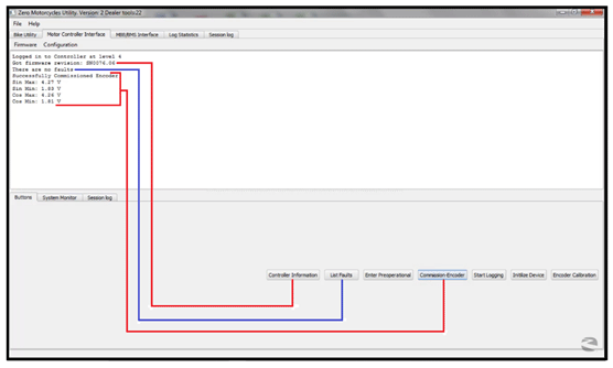
• Encoder Calibration
This is for timing the motor
Important: Ensure the wheel is off the ground!
1. Select the “Encoder Calibration” button and the encoder calibration window will open.
2. If replacing the motor, enter the number, found on the blue tape attached to the motor, to the Encoder Offset field, and press Set Encoder Offset button. If not replacing the motor, go to step 3.
3. Then select the “Start Automated Calibration” button on the encoder calibration window.
4. Then slowly twist the throttle up to about a 1,000 RPM, keeping the dots steady around 10.

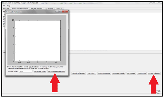
5. The dots will begin to turn from red to blue and automatically adjust the calibration.

6. The calibration is verified by the “Successfully Calibrated Encoder Offset” message. When completed close this window.

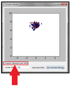
System Monitor Tab
Select this tab to display a live dynamic view of various functions in real time.

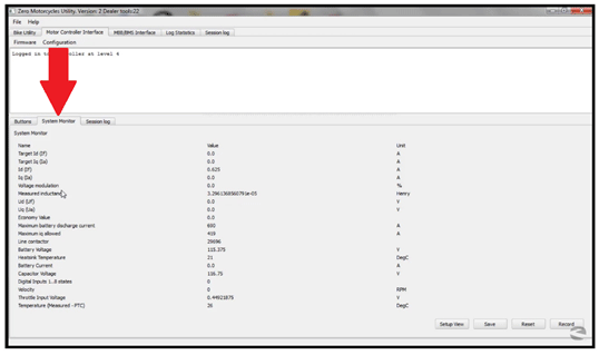
Version 1
This procedure is used to check the firmware revision, pull diagnostic logs, and update individual systems or all systems through one diagnostic port. This greatly reduces the chance of loading non-current firmware, and saves time by going to one location on the motorcycle and one system to perform the update and retrieve the different logs.
The new diagnostic interface is called “Zero Diagnostics Utility” or ZDU. Currently you can run a version check of firmware for all the components (MBB and BMS), and then update them as needed. You can also pull MBB and BMS logs and zip them to a folder for fast emailing to Zero Technical Support for analysis.
1. Double click the desktop icon to start the program.


2. If everything is connected properly and the motorcycle is keyed ON, the ZDU program window will open.
3. With the “Bike Utility” tab selected, press the "Connect To Bike" button. The ZDU will automatically scan available devices for firmware versions.

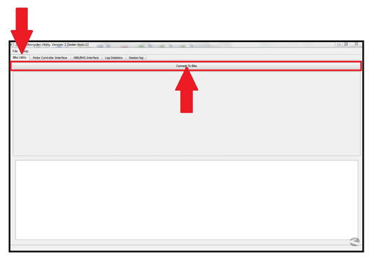
4. Once the scan is complete you will see a summary of devices and firmware versions. If the version number(s) are in red if updates are available.

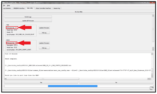
5. Update to the new version, select the “Update Firmware” for an individual devise or “Update All Firmware” for all devises. The newest version of firmware will install and the version number will turn green.

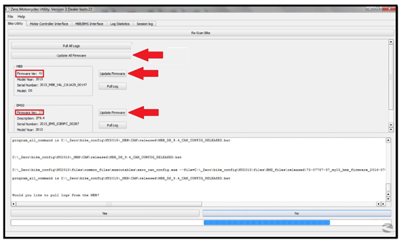
6. You will now be asked if you want to pull logs, use the “Yes” or “No” to select your choice. If you selected “Yes” the firmware will now update. Note: this may take up to 10 minutes to complete.

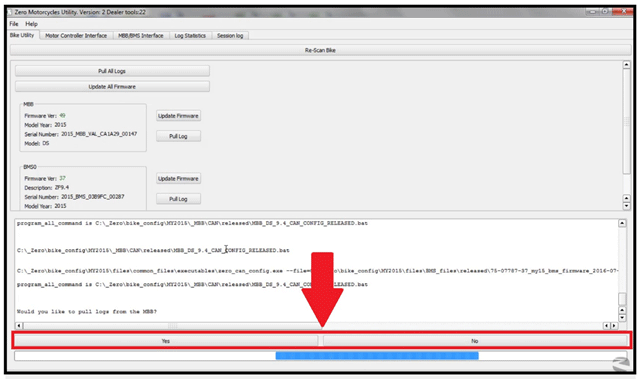
7. When complete select “Re-Scan Bike” to verify that the latest versions have been installed.

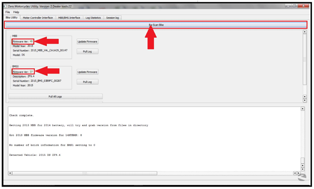
Version 1
This works similar to the tera term.
1. Select the “MBB/BMS Interface” tab at the top of the window then select the “Connect” button at the bottom of the page.

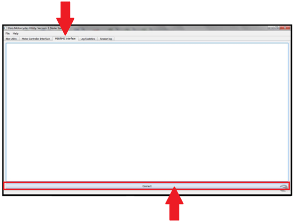
2. Once connected to the motorcycle, type commands in the area at the bottom of the window, then select “Enter”. Type the word “help” will bring up the main menu.

Main Menu Options

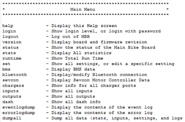
Version 1

